
[1] 납접
납접은 모재의 용융온도보다 낮은 땜납(solder)을 용가재(熔加材; filler metal)로 사용하는 용접이며, 땜납은 용융온도에 따라 대체로 450℃ 이하인 연납(軟납; soft solder)과 450℃ 이상인 경납(硬납; hard solder)으로 분류하고, 미국에서는 427℃를 기준으로 택한다.
납접의 장·단점을 들면 다음과 같다.
- 장점
- 거의 모든 금속을 납접할 수 있다.
- 융점이 다른 이종금속을 납접할 수 있다.
- 가열온도가 낮기 때문에 접합시간이 짧고, energy 소비가 적으며, 열영향의 정도와 범위가 적다.
- 자동화가 용이하다.
- 접합부를 재가열하여 납을 용융시키면 접합부의 분리가 가능하다.
- 단점
- 용가재인 납의 강도가 모재의 것보다 낮기 때문에 접합강도가 낮다.
- 가열에 의하여 접합부가 약화되거나 파손되는 경우가 있다.
-
(1) 연납접(soldering):
-
연납(soft solder)에는
- Sn-Pb 계: 사용범위가 가장 넓고 연납의 대표적인 것이다.
- Sn 계: Sn-Au 계, Sn-Ag 계, Sn-Sb 계 등이 있으며, 주로 반도체의 저온 납접에 사용된다.
- Pb 계: Pb에 소량의 Ag, Sn 등을 첨가한 것으로서 고온연납이다.
- Au 계: Si, Ge 반도체 및 Si chip과 기판의 납접에 사용된다.
등이 있으며, 저온에서 용이하게 납접을 할 수 있는 용가재이나, 기계적 강도가 낮다.
Sn-Pb 계의 연납에서 Sn의 양이 Pb보다 많은 납을 상납(上납)이라 하고, 아래 표는 Sn-Pb 계의 성분과 용도를 예시한 것이다. 얇거나 가느다란 강, 동, nickel 등의 판재 및 선재의 접합에 사용된다. 주철, stainless 강 및 Cr 도금판은 연납접을 할 수 없다.
연납은 강도가 낮기 때문에 큰 접합강도를 요하지 않는 전기부품의 결선 또는 수밀(水密) 및 기밀(氣密)을 요하면서 큰 강도를 필요로 하지 않는 곳의 접합에 많이 사용된다. 연납의 강도가 낮기 때문에 아래 그림과 같이 겹치기 납접을 하거나 기계적으로 물린 상태에서 납접는 경우가 많다.
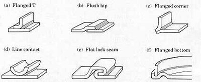 lap soldering
모재의 산화막 등의 불순물을 제거하기 위하여 HCl, NH
4 Cl, ZnCl2 , H3 PO4 등의 용제를 선재의 내부에 넣은 상태와 paste 형태로 사용한다. 연납접 작업은 접합부를 wire brush, 사포(砂布) 등으로 불순물을 제거하고 용제(溶劑; flux)를 사용하여 청소한 다음 목탄(木炭)이나 torch 등으로 가열한 납땜 인두(soldering iron) 또는 전기인두로 납을 접합면에 대고 문질러 접합하며, 접합 후 표면에 묻은 용제를 제거하여 용제에 의한 부식을 방지한다. 제품의 형상 및 접합부의 위치때문에 인두를 사용할 수 없을 때에는 침지법(浸漬法) 또는 화염법(火焰法)을 이용한다.
침지법(浸漬法): 제품을 전부 또는 일부를 납의 용융점보다 20 ~ 30℃ 높은 납욕(lead bath)에 담구어 수 초 내에 접합한다. 담구기 전에 접합부에 용제를 발라 납욕에서 납이 붙도록 한다.
화염법(火焰法): 접합할 부분에 용제를 바르고 제품을 가열판 위에 놓아 torch 등으로 가열판을 가열하면서 분말상의 납을 공급하여 접합한다. soldering kit
  solder and flux
 soldering iron과 fume extractor
  soldering robot
  soldering robot의 twin head
-
(2) 경납접(brazing):
-
경납(soft solder, brazing filler metal)에는 은납, 황동납, 양은납, 금납, 백금납, aluminum 납, 철납 등이 있으며, 이들의 성분과 용도는 다음과 같다.
- 은납(silver solder): 황동에 Ag를 6 ~ 10% 정도 가한 것이며 황동, 동, 연강의 땜에 사용된다. Ag를 가하면 유동성이 양호하고 강도가 커진다.
- 황동납(brass solder): Cu가 40 ~ 50%, 나머지가 Zn이며, 황동, 강, 동의 땜에 사용된다.
- 양은납(German silver solder): 황동에 Ni를 8 ~ 12% 가한 것이며, 동 및 강의 땜에 사용된다.
- 금납(gold solder): Au-Ag-Cu의 합금이며, 금과 은의 땜에 사용된다.
- 백금납(platinum solder): Ag-Au의 합금으로, 내열 및 내식성 등이 우수하며 전자부품, 항공기 및 백금의 땜에 사용된다.
- aluminum 납(aluminum solder): Al-Mg-Zn의 합금이며, Al 금속의 땜에 사용된다.
- 철납(iron solder): 철분, 붕사, 붕산 등의 혼합물이며, 사용온도는 1150
o C 정도이다.
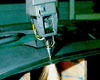
용제로서는 붕사 등을 물로 반죽하여 도포하거나 경납을 접합부상에 놓고 입상(粒狀)의 용제를 살포하여 산화막을 제거한다. 대표적인 용제에는 LiCl, NaCl, KCl, ZnCl₂등이 있다. 경납과 모재의 가열에는 gas burner, torch, ☞ 노(중유로, 전기저항로, 고주파로)를 사용하며, 그림은 bite tip을 몸체(shank)에 경납접하는 예로서 노에 넣어 경납을 용융시킨 후에 유중(油中)에서 냉각시킨다.
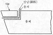 bite의 경납접
  경납
경납
금속의 절단은 chip을 발생하는 기계적인 절단과 열에 의한 용단(熔斷)으로 크게 나눌 수 있다. 용단이 기계적인 절단에 비하여 절단면이 매끄럽지 못하고 용단이 되지 않는 금속이 있지만, 구조상 기계적 절단이 어려운 것을 절단할 수 있어 편리하게 사용되고 있다.
용단은 열원이 전기인 경우와 gas 연소에 의한 것 등으로 분류할 수 있으나, 본 장에서는 gas 연소에 의한 절단 중에서 일반적으로 많이 이용되는 산소-acetylene 절단에 중점을 두어 설명하고자 한다.
[1] arc 절단
☞ arc 절단은 주철, 황동 등과 같이 gas 절단이 어려운 금속의 절단에 편리하며, 용접의 경우보다 큰 전류의 긴 arc를 사용한다.
arc 절단에는
- 탄소 arc 절단: 전극으로 탄소봉을 이용하여 전극과 모재 사이에 발생하는 arc 열에 의한 절단이다.
- 금속 arc 절단: 특수피복 금속봉과 모재 사이에 발생하는 arc 열에 의한 절단으로서, 직류인 경우에는 정극성을 채용한다.
- 산소 arc 절단: 피복전극과 모재 사이에 arc를 발생시키고 심선 중심부의 중공을 통하여 용금을 불어 내어 절단한다.
- ☞ 불활성 gas arc 절단: MIG 용접과 TIG 용접 장치에서 높은 전류밀도를 사용하여 깊은 용입이 되게한다.
- ☞ plasma arc 절단: 도전성을 띤 gas체인 plasma에 의하여 용융시키고 불어 낸다.
[2] laser beam 절단
☞ laser beam 절단은 박판의 절단 및 구멍뚫기에 사용되나, 장비가 고가이고 energy 소비가 크다. 자동차 공장에서 body panel의 trimming 등에 이용된다.
-
 laser 절단
☜ tube1.ram
관의 laser 절단 tube2.ram
관의 laser 절단
[3] gas 절단
대부분의 용단(熔斷)은 산소-gas 절단이며, 비철금속에서는 용단부를 단순이 용해시켜 불어 내는 것으로서 용단이 수행되나, 철의 절단에서는 혼합 gas 염으로 800 ~ 1000℃ 정도로 예열하고 이것에 순도가 높은 산소를 고압으로 분사하면 강열한 화학반응에 의한 고온으로 철은 산화( 연소)되며, 기류가 산화철을 불어 내어 2~4mm 폭의 홈이 생긴다.
이 때의 화학반응은 다음과 같다.
-
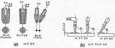 gas 절단 torch의 tip
☜
-
(1) 수동절단:
-
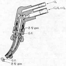
절단 torch에는 예열용 acetylene gas의 압력을 기준으로 하여 저압식(低壓式, 0.07kg/cm2 이하)과 중압식(中壓式, 0.07kg/cm2 이상)이 있으며, 그림은 저압식 torch로서, 예열용 산소-acetylene 혼합 gas 도관과 순수 산소만을 보내는 도관으로 되어 있다.
 gas 절단의 animation
 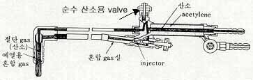 저압식 torch의 구조
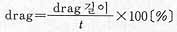
gas 절단에서는 절단홈의 밑으로 갈수록 slag의 방해, 산소의 오염 등에 의하여 산화작용이 느리고, 불어 내는 압력이 저하하기 때문에 그림과 같이 上下의 절단거리에 차이가 생기며, 이 차이를 drag 또는 drag 거리라 한다. 이 drag는 절단성을 판정하는 기준이 되며, 절단속도, 산소소비량 등에 따라 변하고, 절단속도가 아주 느리면 drag는 0 이 된다. 산소량과 산소압력을 증가시키면 drag는 짧아지나, 산소압력을 증가시켜도 더 이상 drag가 짧아지지 않는 한계가 있다. drag가 길게 되는 조건에서 절단하면 절단비용은 감소하나, 절단깊이의 밑부분에서는 절단이 되지 않을 수도 있으므로 drag는 강판두께의 20% 정도가 작업능률의 관점에서 좋다.
-
(2) 자동절단:
-
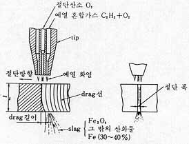
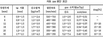
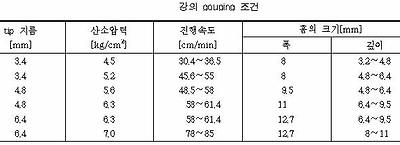
공작물을 절단할 때 절단기가 이동대와 함께 track 위를 자동 이동하면서 직선 또는 곡선절단할 수 있는 자동절단기가 있다. 아래 표의 조건에 따라 강판과 torch tip 간의 거리 등을 선정하고, 절단 시작점을 충분히 예열하여 용융점에 이를 때 순수 산소 valve를 열어 산화, 분출시키면서 이동대를 track상에서 이동시켜 절단한다.
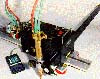 programable 2-axis 용접 및 절단기
☜
 2 ~ 3개의 torch로 홈을 자동절단하는 예
-
(3) 수중 gas절단:
-
수중절단은 침몰선의 해체, 교량의 보수 등 불가피하게 수중 작업을 요하는 곳에서 이용되며, 일반 torch와 다른 점은 그림과 같이 용접 중 물의 침입을 막기 위하여 압축공기를 분출하는 구멍이 하나 더 있다. acetylene gas는 수중 7.5m 깊이까지 사용할 수 있고, 보다 깊은 곳에서는 압력에 의한 안전상 수소 gas를 사용한다.
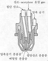 수중 절단 torch tip
-
(4) gas gouging:
-
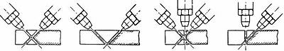
일명 따내기라고도 하며, 가공물의 일부분을 용융시켜 불어 냄으로써 홈을 내는 가공이다. 아래 그림과 같이 gouging torch tip을 30 ~ 45°경사지게 하여 예열하고, 표면이 점화온도에 달하면 tip을 6 ~ 12mm 정도 후퇴시켜 산소 valve를 서서히 열고 작업을 진행한다.
 U형 홈 가공용 gas gouging torch tip
 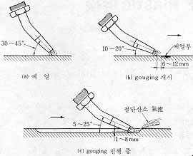 gouging 작업

|
Furnace brazing is a joining process that uses filler metal to join two contacting workpieces. Heat generated by the furnace melts the filler metal and distributes it throughout the joint by capillary action. Process Characteristics |

☞ arc 절단
Metals can be cut cleanly with a carbon electrode arc because no foreign metals are introduced at the arc. The cutting current should be 25 to 50 amps above the welding current for the same thickness of metal.The carbon electrode point should be ground so that it is very sharp. During the actual cutting, move the carbon electrode in a vertical elliptical movement to undercut the metal; this aids in the removal of the molten metal. As in oxygen cutting, a crescent motion is preferred. Figure 7-52 shows the relative positions of the electrode and the work in the cutting of cast iron.

The carbon-arc method of cutting is successful on cast iron because the arc temperature is high enough to melt the oxides formed. It is especially important to undercut the cast-iron kerf to produce an even cut. Position the electrode so the molten metal flows away from the gouge or cutting areas. Table 7-4 is a list of cutting speeds, plate thicknesses, and current settings for carbon-arc cutting. Because of the high currents required, the graphite form of carbon electrode is better. To reduce the heating effect on the electrode, you should not let it extend more than 6 inches beyond the holder when cutting. If the carbon burns away too fast, shorten the length that it extends out of the electrode holder to as little as 3 inches. Operating a carbon electrode at extremely high tempera-tures causes its surface to oxidize and burn away, result-ing in a rapid reduction in the electrode diameter. Carbon-arc cutting does not require special generators. Standard arc-welding generators and other items of arc-welding station equipment are suitable for use. Straight polarity direct current (DCSP) is always used. Because of the high temperature and the intensity of the arc, choose a shade of helmet lens that is darker than the normal shade you would use for welding on the same thickness of metal. A number 12 or 14 lens shade is recommended for carbon-arc welding or cutting.
AIR CARBON-ARC CUTTING
Air carbon-arc cutting (ACC) is a process of cutting, piercing, or gouging metal by heating it to a molten state and then using compressed air to blow away the molten metal. Figure 7-53 shows the process. The equipment consists of a special holder, as shown in figure 7-54, that uses carbon or graphite electrodes and compressed air fed through jets built into the electrode holder. A push button or a hand valve on the electrode holder controls the air jet.


The air jet blows the molten metal away and usually leaves a surface that needs no further preparation for welding. The electrode holder operates at air pressures varying between 60 and 100 psig. During use, bare carbon or graphite electrodes be-come smaller due to oxidation caused by heat buildup. Copper coating these electrodes reduces the heat buildup and prolong their use. The operating procedures for air carbon-arc cutting and gouging are basically the same. The procedures are as follows:
- Adjust the machine to the correct current for electrode diameter.
- Start the air compressor and adjust the regulator to the correct air pressure. Use the lowest air pressure possible-just enough pressure to blow away the molten metal.
- Insert the electrode in the holder. Extend the carbon electrode 6 inches beyond the holder. Ensure that the electrode point is properly shaped.
- Strike the arc; then open the air-jet valve. The air-jet disc can swivel, and the V-groove in the disc automatically aligns the air jets along the electrode. The electrode is adjusted relative to the holder.
- Control the arc and the speed of travel according to the shape and the condition of the cut desired.
- Always cut away from the operator as molten metal sprays some distance from the cutting action. You may use this process to cut or gouge metal in the flat, horizontal, vertical, or overhead positions.
AIR CARBON-ARC GOUGING
Air carbon-arc gouging is useful in many various metalworking applications, such as metal shaping and other welding preparations. For gouging, hold the elec-trode holder so the electrode slopes back from the direc-tion of travel. The air blast is directed along the electrode toward the arc. The depth and contour of the groove are controlled by the electrode angle and travel speed. The width of the groove is governed by the diameter of the electrode. When cutting or gouging a shallow groove on the surface of a piece of metal, you should position the electrode holder at a very flat angle in relation to the work. The speed of travel and the current setting also affect the depth of the groove. The slower the movement and the higher the current, the deeper the groove. An example of a V-groove cut made in a 2-inch-thick mild steel plate by a machine guided carbon-arc air-jet is shown in figure

METAL ELECTRODE ARC CUTTING>
Metal can be removed with the standard electric arc, but for good gouging or cutting results, you should use special metal electrodes that have been designed for this type of work, Manufacturers have developed electrodes with special coatings that intensify the arc stream for rapid cutting. The covering disintegrates at a slower rate than the metallic center. This creates a deep recess that produces a jet action that blows the molten metal away (fig. 7-56). The main disadvantage of these electrodes is that the additional metal produced must be removed.

These electrodes are designed for cutting stainless steel, copper, aluminum, bronze, nickel, cast iron, man-ganese, steel, or alloy steels. A typical gouge-cutting operation is shown in figure 7-57. Notice that the angle between the electrode and plate is small (5 degrees or less). This makes it easy to remove the extra metal produced by the electrode.

The recommended current setting is as high as the electrode will take without becoming overheated to the point of cracking the covering.
- For 1/8-inch electrodes, the setting ranges between 125 and 300 amperes
- For 5/32-inch electrodes, the setting ranges between 250 and 375 amperes
- For 3/16-inch electrodes, the setting ranges between 300 and 450 amperes
Usee a very short arc, and when cutting takes place underwater, the coat-ing must be waterproof.
Plasma Arc Cutting
Plasma arc cutting can increase the speed and efficiency of both sheet and plate metal cutting operations. Manufacturers of transportation and agricultural equipment, heavy machinery, aircraft components, air handling equipment, and many other products have discovered its benefits. Plasma cutters are used in place of traditional sawing, drilling, machining, punching, and cutting. The high-temperature plasma arc cuts through a wide variety of metals at high speeds. Although plasma arc cutting can cut most metals at thicknesses of up to 4 to 6 inches, it provides the greatest economical advantages, speed, and quality on carbon steels under 1 inch thick, and on aluminum and stainless steels under 3 inches thick. Plasma arc cutting has gained approval in both hand-held and automated cutting operations. Some of the most impressive results are achieved in automated systems. Advances in computer numerical controls (CNC), robots, and other automation techniques have offered manufacturers higher cutting speeds achieved through plasma arc cutting. Improved torch designs and more efficient power supplies have made plasma arc cutting increasingly popular. New areas of technology in plasma arc cutting systems include non-transferred arc plasma, which allows plastics and other nonconductive materials to be cut. Research on cutting plastics is continuing and at least one commercial process is currently available.

Oxygen Arc Cutting (AOC)
(1) Oxygen arc cutting severs metals by means of the chemical reaction of oxygen with the base metal at elevated temperatures. The necessary temperature is maintained by means of an arc between a consumable tubular electrode and the base metal. (2) This process requires a specialized combination electrode holder and oxygen torch. A conventional constant current welding machine and special tubular covered electrodes are used. (3) This process will cut high chrome nickel stainless steels, high-alloy steels, and nonferrous metals. (4) The high temperature heat source is an arc between the special covered tubular electrode and the metal to be cut. As soon as the arc is established, a valve on the electrode holder is depressed. Oxygen is introduced through the tubular electrode to the arc. The oxygen causes the material to burn and the stream helps remove the material from the cut. Steel from the electrode plus the flux from the covering assist in making the cut. They combine with the oxides and create so much heat that thermal conductivity cannot remove the heat quickly enough to extinguish the oxidation reaction. (5) This process will routinely cut aluminum, copper, brasses, bronzes, Monel, Inconel, nickel, cast iron, stainless steel, and high-alloy steels. The quality of the cut is not as good as the quality of an oxygen cut on mild steel, but sufficient for many applications. Material from 1/4 to 3 in. (6.4 to 76 mm) can be cut with the process. The electric current ranges from 150 to 250 amperes and oxygen pressure of 3 to 60 psi (20.7 to 413.7 kPa) may be used. Electrodes are normally 3/16 in. (4.8 mm) in diameter and 18 in. (457 mm) long. They are suitable for ac or dc use. This process is used for salvage work, as well as for manufacturing and maintenance operations.
불활성 gas arc 용접(不活性 gas arc 熔接; shield inert gas arc welding):
대기 중의 산소와 질소의 영향을 받지 않도록 argon(Ar)이나 helium(He)과 같이 고온에서도 금속과 반응을 하지 않는 불활성 gas 중에서 시행하는 용접을 불활성 gas arc 용접이라 한다. 이 용접법의 개발로 인하여 종래에 용접이 곤란하거나 불가능했던 금속의 용접이 용이해지거나 가능해졌다. 이 용접법은 Al 합금, Mg 합금, Cu 합금, Ni 합금, Ti 합금 등의 용접에 많이 이용된다.
불활성 gas arc 용접법의 장단점은 다음과 같다.
장점
- 대체로 모든 금속의 용접이 가능하다.
- 용제를 사용하지 않으므로 slag가 없어 용접 후 청소가 필요 없다.
- spatter의 발생이 적고, 합금원소의 손실이 적다.
- 전자세(全姿勢)의 용접이 가능하다.
- 용접 가능한 판의 두께 범위가 크다.
- 용접 능률이 높다.
단점
- 용접 비용이 크다.
불활성 gas arc 용접은 불활성 gas 분위기에서 모재와 용가재 사이에 arc를 발생시키는 불활성 gas 금속 arc 용접(metal inert gas arc welding, MIG 용접)과 tungsten 전극과 모재 사이에 arc를 발생시키고 용가재를 별도로 공급하는 불활성 gas tungsten arc 용접(tungsten inert gas arc welding, TIG 용접)이 있다.
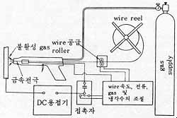
(2-1) MIG 용접:
MIG 용접을 용극식(熔極式) 불활성 gas arc 용접 또는 소모식(消耗式) 불활성 gas arc 용접이라고도 하며, 상품명으로 aircomatic 용접 및 sigma 용접 등이 있다. 용접기는 전동발전기식과 정류기식의 직류용접기이고, 모재를 음극으로 하는 역극성(逆極性)을 많이 채용한다. 동일 전류에서 arc 전압이 크게 되면 용융 속도가 저하한다. arc가 길어지면 전압이 증가하여 용융속도가 감소하므로 wire가 일정 속도로 공급될 때 arc 길이가 짧아져 원래의 길이로 되돌아간다. 이와 반대의 경우에도 원래의 길이로 돌아가며, 이를 MIG 용접 arc의 자기제어(自己制御)라 한다.
MIG 용접은 TIG 용접에 비하여 arc가 집중적이며, 용융속도가 크고, 응고속도가 커서 gas와 불순물이 부유할 시간적 여유가 없기 때문에 기공과 편석이 생길 염려가 있다. 따라서 용접하기 전에 모재를 깨끗이 청소하고, wire는 기공의 원인이 되는 수분이 없도록 충분히 건조시켜 사용하는 것이 중요하다.
 MIG 용접기 MIG 용접기 |
 MIG 용접 MIG 용접 |
(2-2) TIG 용접:
TIG 용접을 비용극식(非熔極式) 불활성 gas arc 용접 또는 비소모식(非消耗式) 불활성 gas arc 용접이라고도 하며, 전원으로는 교류 및 직류를 사용할 수 있으나, 직류를 사용할 때에는 극성의 선택에 유의하여야 한다. tungsten 전극은 극성과 gas의 종류에 의하여 재질 및 크기가 정해져 있다.
정극성을 택하면 모재의 용입이 깊고 bead 폭이 넓게 되며, 역극성으로 하면 가속된 gas ion이 모재에 충돌하여 청정작용을 한다. He은 Ar에 비해 가볍기 때문에 청정효과가 적다. 따라서 aluminum은 표면에 2050℃에서나 녹는 내화성(耐火性) 산화물인 Al2O3가 있기 때문에 일반용접에서는 곤란하나, 불활성 gas arc 용접에서는 역극성으로 용제 없이도 쉽게 용접할 수 있다. 교류용접은 직류의 정극성과 역극을 혼합한 것이라 볼 수 있으며, wire 지름은 비교적 작은 편이고, 경합금(輕合金) 등의 표면에 있는 산화물을 청정하여 용입이 얕은 용접을 하기에 알맞다.
 TIG 용접기 TIG 용접기 |
 TIG 용접 TIG 용접 |
☞ plasma arc 절단
Cutting processes - plasma arc cutting - process and equipment considerations
| Photo courtesy: Goodwin Plasma |
 |
Process fundamentals
The plasma arc cutting process is illustrated in Fig. 1. The basic principle is that the arc formed between the electrode and the workpiece is constricted by a fine bore, copper nozzle. This increases the temperature and velocity of the plasma emanating from the nozzle. The temperature of the plasma is in excess of 20 000°C and the velocity can approach the speed of sound. When used for cutting, the plasma gas flow is increased so that the deeply penetrating plasma jet cuts through the material and molten material is removed in the efflux plasma.
 |
Fig.1. The plasma arc cutting process |
The process differs from the oxy-fuel process in that the plasma process operates by using the arc to melt the metal whereas in the oxy-fuel process, the oxygen oxidises the metal and the heat from the exothermic reaction melts the metal. Thus, unlike the oxy-fuel process, the plasma process can be applied to cutting metals which form refractory oxides such as stainless steel, aluminium, cast iron and non-ferrous alloys.
Power source
The power source required for the plasma arc process must have a drooping characteristic and a high voltage. Although the operating voltage to sustain the plasma is typically 50 to 60V, the open circuit voltage needed to initiate the arc can be up to 400V DC.On initiation, the pilot arc is formed within the body of the torch between the electrode and the nozzle. For cutting, the arc must be transferred to the workpiece in the so-called 'transferred' arc mode. The electrode has a negative polarity and the workpiece a positive polarity so that the majority of the arc energy (approximately two thirds) is used for cutting.
Gas composition
In the conventional system using a tungsten electrode, the plasma is inert, formed using either argon, argon-H2 or nitrogen. However, as described in Process variants, oxidising gases, such as air or oxygen, can be used but the electrode must be copper with hafnium.The plasma gas flow is critical and must be set according to the current level and the nozzle bore diameter. If the gas flow is too low for the current level, or the current level too high for the nozzle bore diameter, the arc will break down forming two arcs in series, electrode to nozzle and nozzle to workpiece. The effect of 'double arcing' is usually catastrophic with the nozzle melting.
Cut quality
The quality of the plasma cut edge is similar to that achieved with the oxy-fuel process. However, as the plasma process cuts by melting, a characteristic feature is the greater degree of melting towards the top of the metal resulting in top edge rounding, poor edge squareness or a bevel on the cut edge. As these limitations are associated with the degree of constriction of the arc, several torch designs are available to improve arc constriction to produce more uniform heating at the top and bottom of the cut.Process variants
The process variants, Figs. 2a to 2e, have principally been designed to improve cut quality and arc stability, reduce the noise and fume or to increase cutting speed.Dual gas
| Fig.2a. dual gas |
 |
- Steel
- air, oxygen, nitrogen
- Stainless steel
- nitrogen, argon-H2, CO2
- Aluminium
- argon-H2, nitrogen / CO2
- Reduced risk of 'double arcing'
- Higher cutting speeds
- Reduction in top edge rounding
Water injection
| Fig.2b. water injection |
 |
The advantages compared with conventional plasma are:
- Improvement in cut quality and squareness of cut
- Increased cutting speeds
- Less risk of 'double arcing'
- Reduction in nozzle erosion
Water shroud
| Fig.2c. water shrouded |
 |
- Fume reduction
- Reduction in noise levels
- Improved nozzle life
As the water shroud does not increase the degree of constriction, squareness of the cut edge and the cutting speed are not noticeably improved.
Air plasma
| Fig.2d. air plasma |
 |
It should be noted that although the electrode and nozzle are the only consumables, hafnium tipped electrodes can be expensive compared with tungsten electrodes.
High tolerance plasma
| Fig.2e. high tolerance |
 |
- Cut quality lies between a conventional plasma arc cut and laser beam cut
- Narrow kerf width
- Less distortion due to smaller heat affected zone
This article was prepared by Bill Lucas in collaboration with Derrick Hilton, BOC
☞ laser beam
laser beam 용접
laser는 빛의 증폭기(增幅器; light amplifier)를 말하며, 정확한 어원은 유도방사(誘導放射)에 의한 빛의 증폭기(light amplification by stimulated emission of radiation)이다. 그림과 같이 크세논 섬광관(xenon flash tube)에서 발생하는 섬광(flash)이 rubby 결정(結晶, Al2O3+15% Cr) 중의 Cr 원자에 의하여 자려발진(自勵發振)이 일어나고, 결정을 지나는 중에 증폭되어져 아주 격렬한 빛으로 된다. 이 빛을 lens를 통하여 집중시킨 열 energy를 이용한 용접을 laser 용접이라 한다. 이 용접의 특징은 다음과 같다.
-
- 진공실이 필요없다.
- 좁고 깊은 접합에 적합하며, 특히 얇은 부품의 용접에 유리하다.
- 변형과 수축이 적다.
- 용접속도가 크고, CNC 등에 의한 자동화가 쉽다.
- 가까이 접근할 수 없는 부재(部材)의 용접을 할 수 있다.
- 다양한 재료의 용접이 가능하며, 용접재가 부도체인 경우도 용접이 가능하다.
- 미세정밀(微細精密)용접을 할 수 있다.
- 대부분 용가재를 사용하지 않고 모재의 합금화에 의한다.
- 이종재료의 용접도 성공적으로 수행할 수 있다.
 laser 용접 예
  plastic의 laser 용접 모형
 laser 용접의 원리