이 역시 여러분 선배님들 프로젝트용 입니다.
SAMD21 MIcrocontroller
The heart of the tiny Seeeduino XIAO is the Atmel ATSAMD21 Cortex M0+ 32-bit microcontroller from Microchip. This tiny wonder has been around since 2012 and it has the following specifications:
- 32-bit single-core processor
- Clock speed up to 48MHz
- 32KB SRAM
- 256KB Flash Memory
- 11 Digital I/O
- 11 12-bit ADC Inputs
- 1 DAC Output
- Support for up to 120 touch channels
- USB Device and Embedded host
- Hardware RTC
- 1.62V to 3.63V power supply
- Extremely low power consumption
- 6 serial communication modules (SERCOM) configurable as UART/USART, SPI or I2C
This processor is used in a number of other microcontroller boards, including the Arduino Zero , Arduino MKRZero and Arduino MKR 1000 boards. Seeedstudio also makes the Seeeduino Cortex-M0+ and Seeeduino Lotus Cortex-M0+, both of which support Grove connectors. Adafruit and Sparkfun also make boards using the SAMD21 microcontroller.
Seeeduino XIAO Pinouts
The Seeeduino XIAO is a tiny module with 14 output pins, as well as a few other surface connections.
Unlike most modules, the pins on the XIAO are numbered starting at 0 instead of 1, so the pins range from 0 to 13. This allows the pin numbers to correspond to the port numbers for the digital I/O and analog input connections.
Most of the pins on the Seeeduino XIAO serve multiple functions, so it is easier to examine them by dividing them into functional groups.
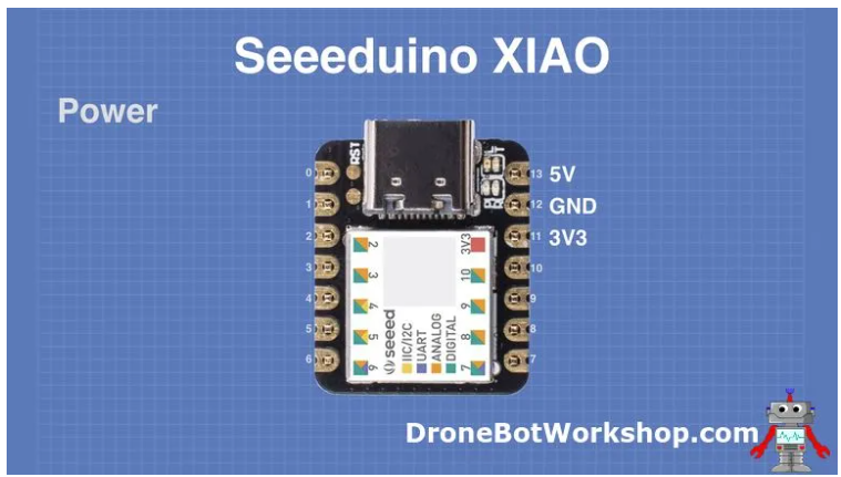
Power Connections
The ATSAMD21G18 processor is a 3.3-volt device, however, the XIAO has an onboard XC6206P3232MR DC-DC Power Converter to allow the board to be powered by 5-volts as well.
There are actually a few different ways of powering the Seeeduino XIAO:
- The USB-C connector powers the XIAO from the attached computer.
- You can apply 5-volts to pin 13, this will be reduced to 3.3-volts by the internal DC-DC converter.
- You can apply 3.3-volts to pin 11.
- You can use the VCC and GND connections underneath the XIAO and apply 3.7 to 5-volts. This is an ideal method of powering the XIAO with a small LiPo battery.
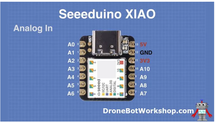
Analog Input Connections
The Seeeduino XIAO has 11 analog inputs, each connected to a 12-bit A/D converter.
Note that the maximum voltage you can apply to these inputs is 3.3-volts.
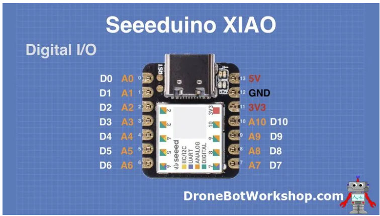
Digital I/O Connections
The XIAO also has 11 digital I/O pins, sharing the same pins as the analog inputs.
Remember, the Seeeduino XIAO I/O pins are 3.3-volt logic, and they are NOT 5-volt tolerant! If you need to interface with 5-volt logic devices you’ll need to use a level converter to avoid damaging the XIAO.
Other Connections
Many of the other pins on the XIAO module have additional functions.
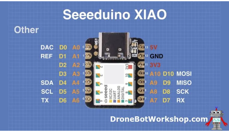
- DAC – (Pin 0) – This is the output of the Digital to Analog converter, which produces an analog output of 0 to 3.3-volts.
- REF – (Pin 1) – This is the Reference Voltage for the 11 Analog to Digital Converters used by the analog inputs. It’s the equivalent of the AREF pin on the Arduino, and can accept a maximum of 3.3-volts.
- SDA – (Pin 4) – The I2C Data line. Note the similar pinout to the Arduino Uno, which also used A4 as SDA.
- SCL – (Pin 5) – The I2C Clock line. Again this is the same pinout as the Uno.
- TX – (Pin 6) – The UART Transmit line.
- RX – (Pin 7 ) – The UART Receive line.
- SCK – (Pin 8) – The SPI bus clock line.
- MISO – (Pin 9) – Master In Slave Out for the SPI bus.
- MOSI – (Pin 10) – Master Out Slave In for the SPI bus.
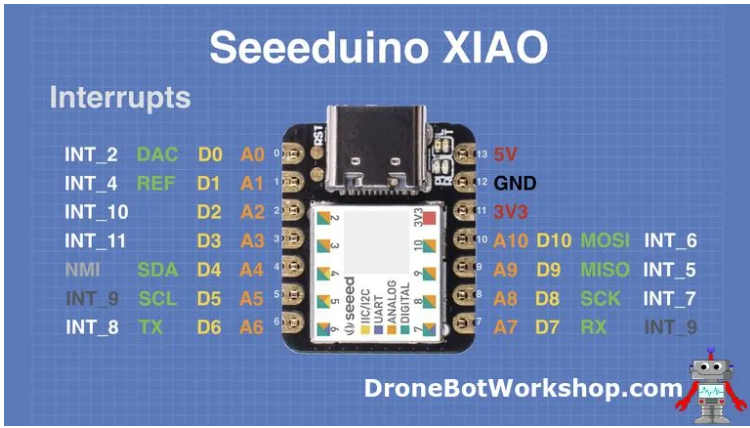
Interrupts
Every pin on the Seeeduino XIAO can be used as an interrupt.
As you can see from the above illustration each pin has been assigned an interrupt number. However, before working with interrupts there are a few issues you need to be aware of:
- Most of the interrupts are “maskable”, in other words, you can programmatically choose to ignore them.
- The interrupt on pin 4 is non-maskable, it cannot be ignored programmatically.
- Pins 5 and 7 share the same interrupt (INT_9).
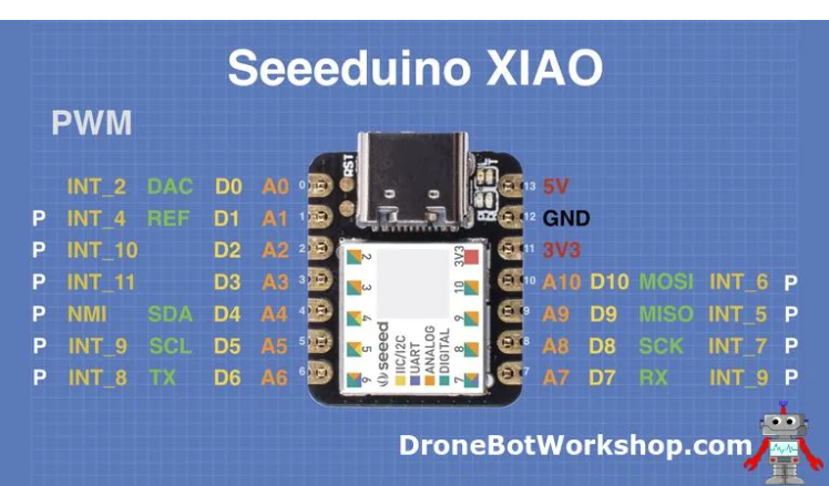
Pulse Width Modulation (PWM)
With the exception of pin 0, all of the pins on the Seeeduino XIAO support PWM.
This makes the XIAO an ideal controller for LED’s, perfect for advanced wearable projects.
Other Features
In addition to the pinouts, we just covered there are a few other connections on the XIAO, as well as some indicator LEDs.
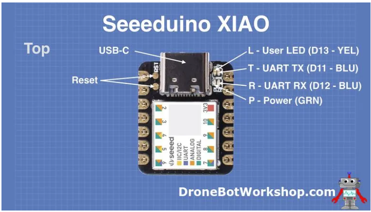
Top
The top of the Seeeduino XIAO has a number of prominent features.
The most prominent feature on the top of the XIAO is the USB-C connector. This is used for both power and data transfer.
To the left of the USB-C connector, you’ll see two pads labeled “RST”. The XIAO does not have a reset switch, instead, you need to short these two pins together to perform a reset.
You can do much more with these pins, by resetting twice in quick succession you can have the XIAO load a fresh copy of the bootloader.
To the right of the USB-C connector you’ll see four tiny surface-mount LEDs, labeled as follows:
- L – (D13) – This is the User or Built-in LED. It is connected to data I/O pin 13, just as the built-in LED on the Arduino Uno is. This LED is yellow.
- T – (D11) – This is the Transmit LED, it indicates transmit activity on the USB-C bus. It may also be addressed as data I/O pin 11. This LED is blue.
- R – (D12) – This is the Receive LED, indicating activity on the USB-C bus. It may also be addressed as data I/O pin 12. This LED is also blue.
- P – This is the power indicator, the LED is green.
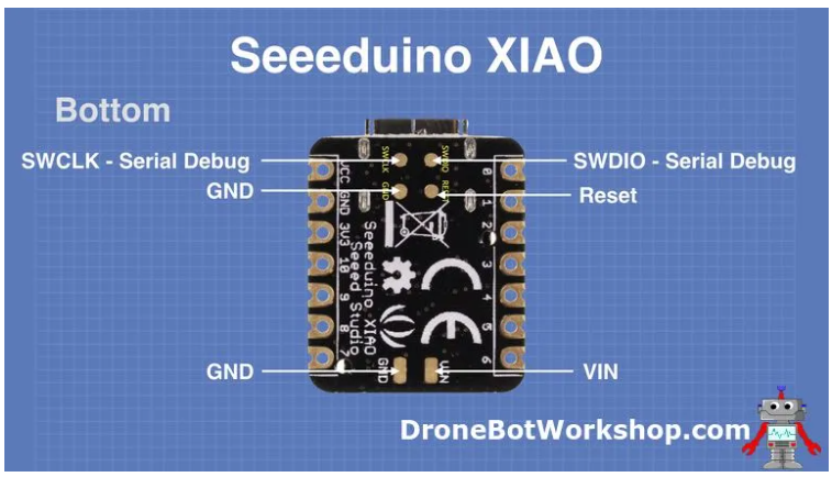
Bottom
The underside of the Seeeduino XIAO also has a few extra pads for additional connections.
- The SWCLK and SWDIO pads are the clock and data lines for the Serial Debug feature.
- There are Reset and Ground pads, this duplicates the functionality of the pads on the top of the XIAO.
- VIN and Ground were previously mentioned. This is another method of connecting power to the XIAO.
https://dronebotworkshop.com/seeeduino-xiao-intro/

https://m.blog.naver.com/emperonics/222201089460
