용접설계
1. 안전율
용접이음의 안전율에 영향을 미치는 인자로는 다음사항이 고려되어야 한다.
◆ 모재 및 용착금속의 기계적성질 (항복점, 인장강도 및 연신, 압축 및 충격치)
◆ 재료의 용접성
◆ 시공조건 (용접공의 기능정도, 용접방법, 용접자세, 이음의 종류와 형상,
작업장소, 용접후 열처리관계, 비파괴 시험의 유무 등)
◆ 하중의 종류(정, 동, 진동하중)와 온도 및 분위기
2. 허용응력
강재의 허용응력으로는 보통 정하중에 대하여 인장강도의 1/4의 값(연강에서는 항복점의 약1/2)이 취해지고 있으며 최근 고항복점을 갖는 고장력강에 대하여는 인장강도의 1/3(항복점의 약40%)의 응력이 쓰인다. 이것은 구조물이 부하를 받았을 때에 재료가 항복하지 않는 것을 전제로 한 소위 탄성설계(elastic design)에 의한 것이다.
3. 용접설계시 유의점
(1) 용접에 적합한 설계를 해야한다.
(2) 가능한한 아래보기 용접이 되도록 한다.
(3) 용접길이는 될 수 있는대로 짧게, 또한 용착량도 강도상 필요한 최소한으로
한다. 용접선을 감소시키기 위하여는 광폭의 판을 이용, 또는 간단한
주단조부품을 병용하는 것이 좋은 경우가 있으며 또한 용접량이 과대하게
되면 변형이 증대하고 관대한 덧붙이는 오히려 피로강도를 저하시켜 유해하다.
(4) 용접이음형상에는 많은 종류가 있으므로 그 특성을 잘 알아서 선택한다.
(5) 용접하기 쉽도록 설계해야 한다. (용접간격고려)
(6) 용접이음이 한곳에 집중되지 않게한다. (용접선이 겹치지 않게한다.)
(7) 결함이 생기기 쉬운 용접은 피해야 하며 약한 필렛용접은 하지 않아야
한다. (스티프너 사용, 돌림용접)
4. 용접설계시 반영하여야 할 특정항목
(1) 용접열 영향을 회피하기 위한 필요 최소거리
(2) 용접이음의 열영향과 인장강도의 관계
(3) 용접이음의 열영향과 충격강도의 관계
(4) 모재두께가 다른 접합부의 용접
(5) 플랜지 용접접합 부분의 응력집중방지
(6) 용접후 표면다음질과 피로방지
(7) 용접부의 비파괴검사방법 지정
5. 용접열 영향을 회피하기 위한 필요 최소거리
(1) 필릿용접·맞대기용접·에지용접이음의 어느 경우에도 접합부에서 대략
판두께(t)의 2배 이상을 떼는 것이 원칙이다.
열영향이 미치지 않는 거리를 판두께(t)의 2배 이상으로 잡는 이유는 필릿용접의 경우, 접합부의 강도를 확보하기 위하여 용접요압부의 「목차수」를 최저 판두께분 이상으로 확보할 필요가 있기 때문이다.
◆ 필릿이음의 경우에는 용입량으로서의 「목차수」
대신에 판두께로 환산해도 된다.
◆ 맞대기 용접의 경우에는 직접 부재 판두께의 2배 이상을 떼어 놓는다.
다만, 용입량이 판두께를 상회하는 경우에는 용입치수로 설정한다.
◆ 에너지용접이음의 경우에는 접합부에서 굽힘 가공부까지의 거리를,
원칙적으로 직접 용입량으로서의 「목차수」로 설정한다.
목차수가 판두께보다 작을 경우에는 부재의 판두께(t)에 따라 설정한다.
(2) 부재에 굽힘가공이 수반되는 경우에는 굽힘가공부의 반경부분을 피하고
직선부를 기점으로하여 접합위치까지의 거리를 설정한다.
(3) 맞대기 용접이음에 걸리는 하중이 정적 인장하중인가, 반복 충격하중인가
에 따라 용접법을 포함한 설계상의 대응을 바꾸어야 한다. 설계상의 대응을
적절히하지 않으면 용접부의 파손 등 트러블이 일어나는 설계를 할 가능성
이 높다.
(4) 일반적으로 맞대기용접 이음의 설계에서는 용접후 풀림처리로 용접 주변부
의 열영향을 변화시켜 파단 등의 트러블 발생을 사전에 예방하는 것이
바람직하다.
6. 용접이음의 열영향과 충격강도의 관계
(1) 맞대기용접 이음을 사용하는 경우에는 부재의 접합부가 되는 용접금속부를
중심으로하여 그 인접 주변부에서 용접열에 의하여 조립역, 세립역, 취화역
이 형성되고 충격강도 등의 기계적 성질이 현저히 저하하는 부분이 발생하
므로 대응설계를 하여야 한다.
(2) 맞대기용접 이음의 접합부는 용접금속을 용융하여 메우는 형대를 취한다.
따라서 용접금속 용입시의 온도는 1400℃ 부근까지 상승한다. 이 열영향은
부재의 접합부에서 어떤 치수범위까지 미친다는 것을 알고 설계할 필요가
있다.
(3) 반복 충격하중이 걸리는 제품·부품에서 밍대기용접 이음을 사용할 경우,
연강재에서는 용접 금속부에 인접하는 졸힙여과 취화역에서 충격강도가
현저히 저하된다. 따라서 용접한 그대로의 상태로 사용하는 것은 바람직
하지 못하다. 용접한대로 사용할 경우에는 용접에 의한 열영향을 그대로
남기는 형대가 된다. 따라서 용접시의 열영향을 가능하면 제거하고 사용
하도록 한다.
(4) 용접시의 열영향을 제거하는 통상적인 방법으로서는 용접후 풀림처리를
하여 조립역과 취화역의 기계적 성질 저하부분을 개선한 다음 사용하는
것이 바람직하다.
7. 모재두께가 다른 접합부의 용접
(1) 모재의 치수가 다른 부분의 접합이 필요한 경우도 많다. 모재의 치수,
즉 판두께(t)에 큰 차이가 있는 부분을 접합할 경우에는 하중에 의한
응력이 접합부에 집중된다. 또, 접합부, 즉 용접금속 주변부에는 열영향에서
기계적 성질이 일부 열화되는 부분도 존재한다. 응력이 집중하고 그 장소에
강도상으로 열화하는 부분이 존재하면 당연히 접합부에서 응력을 지지하지
못하게 되어 균열이 생기고 최종적으로는 파손사고에 이른다. 이를 방지
하기 위해서는 접합부에 응력이 집중하지 않도록 설계하여야 한다.
◆ 그 방법은 접합할 개소의 부재치수를 맡추되 두꺼운 쪽의 부재치수를 얇은
쪽의 부재치수에 맞추는 것이다.
◆ 접합부의 부재치수가 달라서 맞추지 않아도 되는 경우란, 두꺼운 쪽의 부재
치수와 얇은 쪽의 부재 치수치가 10㎜ 이내이거나 판두께치가 2배 이내일
때이다. 이와같은 경우에는 용접금속 덧살부에 직접 경사를 붙여 접합해도
무방하다.
◆ 부재의 치수가 달라 두꺼운 쪽의 부재치수를 얇은 쪽의 부재치수로 맞출
때에 접합부를 향하여 부재에 직접 경사를 붙여도 되나 경사도는 되도록
작은 편이 바람직하다.
(2) 두꺼운 쪽의 부재에 붙이는 경사는 판두께분 이상의 병행부에서 끝으로
설치한다. 이 경우, 병행부에서 경사부로 이동하는 부분은 병행부와 경사부
의 근원부에 응력이 집중하지 않도록 배려하는 것도 중요한 일이다.
8. 플랜지 용접접합 부분의 응력집중방지
(1) 플릿용접에 한하지 않고 맞대기용접·에너지용접에서도 용접부 주변에는
반드시 열영향부가 생기게 마련이다. 나중에 풀림에 의한 용접시의
잔류응력 제거와 용접에 의한 부재의 조직 변질부에 대한 개질을 제대로
하지 않으면 피로강도나 충격강도 등 기계적 성질이 저하하거나 취화역
부분에 응력이 집중하여 균열발생에 의한 파손사고 등의 트러블로 이어진다.
(2) 용접 구조물의 리브와 플랜지의 하중별로 대응하는 가장좋은 배치와 용접법
은 리브와 프랜지를 가급적이면 1부분에 집중시키지 않도록한다. 1부분에의
집중을 피하는 것은 하중에 따른 응력의 집중을 피하는 것이 목적이다. 또,
동시에 리브용접에 수반하는 잔류응력의 집중을 피한다는 의미도 포함되어
있다. 한편, 리브의 집중개소에 있어서의 잔류 내부응력을 분산시키기
위해서는 용접후에 풀림처리를 할 필요가 있다.
9. 용접후 표면다듬질과 피로방지
설계에서 본 경험법칙 적용상의 주의점
(1) 용접 구조물의 설계에서는 구조체의 측면에 함부로 부속품을 용접 고정
에서는 안된다. 구조체의 측면에 부속품을 용접 고장하면 부속품 부분에
직접 하중이 걸리지 않더라도 구조체의 피로강도가 극단적으로 저하되는
현상을 나타내기 때문이다.
(2) 한편, 부득이하여 부속품을 용접 고정하지 않을 수 없을 때는 용접후 전체
를 다듬질 가공하면 어느정도 피로강도의 저하를 억제할 수 있다. 따라서
어쩔 수 없이 구조체 측면에 부속품 설치를 용접으로 할 경우에는 용접후
구조체 전체를 다듬질 가공하여 용접 비드부가 그대로 표면에 노출되지
않도록 할 필요가 있다. - 부속품을 용접 고정하더라도 용접후에 다듬질
가공을 확실하게 하면 피로강도의 저하를 60% 정도로 억제할 수 있다.
(3) 따라서, 구조체의 측면에 부속품을 용접 고정할 때에는 원칙적으로 용접후
다듬질가공을 하는 설계로 하는 것이 중요하다. 또한, 가능하다면 구조체의
측면에는 부속품을 용접 고정하지 않는 설계로 하는 것이 바람직하다.
10. 용접부의 비파괴검사방법 지정
(1) 용접구조물을 설계할 때에는 이음 등의 접합부에서 용접결함이 생길
가능성이 많다는 사실을 염두에 두고 설계하여야 한다.
(2) 용접부에 대한 결함유무의 검사와 시험법을 반드시 도면상에 함께 지정한다.
(3) 용접결함이 잠재할 경우에는 본래의 기계적 성질이 저하된다는 사실을
알고 접합부에서 결함도가 생긴 경우에도 기계적 성질로서의 강도를
확보할 수 있도록 설계허용값을 낮게 설정하는 것이 중요하다.
(4) 용접결함 상태의 판정에는 침투탐상시험, 자기탐상시험, 방사선탐상시험,
초음파탐상시험, 와류탐상시험, 서모그래피, 전기저항법, AE시험 등 결함의
내용에 따라서 구분 사용하고 있다. 또한, X선 투과시험은 방사선 탐사시험
중의 한가지 방법이다.
11. 용접 균열의 방지대책
용접금속의 수축에 의한 인장응력 때문에 균열이 발생되는데 용접금속의 형상, 크기, 이음형식, 구속의 정도등이 영향을 미치게 된다.
A. 용접금속의 균열방지
(1) 적당한 용접봉과 모재의 선택
(2) 적당한 용접설계
(3) 적당한 예열과 후열
(4) 적당한 용접조건과 용접순서
(5) 응력이완법
B. 균열에 나쁜영향을 미치는 수소량 감소방법
(1) 용접봉의 건조와 모재의 수분을 제거
(2) 예열과 후열로 수소의 확산을 피함.
(3) 습기가 많은 곳에서는 용접을 피함.
12. 용접 변형의 방지대책
맞내기 용접 이음에서의 홈 용접 시공은 비대칭 X형 및 H형 홈으로하여 가능한 지름이 큰 용접봉을 사용하고 용착 단면적을 작게하는 것이 좋다.
A. 회전변형의 방지 대책
(1) 용접이 시작될 때 회전 변형이 일어나기 쉬우므로 주의를 요한다.
(2) 가접을 완전하게 하거나 미리 수축을 예측하고 그만큼 벌려 놓는다.
(3) 필용에 따라 용접 끝부분을 구속한다.
(4) 길이가 긴 경우는 두명이상의 용접사가 이음의 길이를 정하여 놓고 동시에
용접한다.
(5) 대칭법, 후퇴법, 비석법(skip method) 등의 용착법을 이용한다.
(6) 맞대기 이음이 많은 경우 길이가 길고 용접선이 직선일 때 또, 제작개수가
많은 부재는 큰 판으로 맞대기 용접한 후 기계적으로 절단가공하면 회전
변형을 감소시킬 수 있다.
B. 각 변형의 방지 대책
(1) 개선 각도는 작업에 지장이 없는 한도 내에서 작게 하는 것이 좋다.
(2) 판 두께가 얇을수록 첫 패스측의 개선깊이를 크게한다.
(3) 판 두께와 개선 형상이 일정할 때 용접봉 지름이 큰 것을 이용하여 패스
수를 줄인다.
(4) 용착 속도가 빠른 용접방법을 선택한다.
(5) 구속 지그를 활용한다.
(6) 역 변형 시공법을 이용한다.
용접 기호 만들기
-
용접 기호에서 화살표 셰이프 중 하나를 드로잉 페이지로 끌어다 놓습니다.
화살표(지시선)가 용접 조인트를 가리키도록 화살표 셰이프의 위치를 지정합니다.
- 다음 중 하나 또는 둘 다를 수행하여 화살표 셰이프를 구성합니다.
- 화살표 셰이프를 마우스 오른쪽 단추로 누르고 원 표시를 선택하여 전방향 용접 기호를 추가합니다.
- 화살표 셰이프를 마우스 오른쪽 단추로 누르고 꼬리 표시를 선택하여 참조선에 꼬리를 추가합니다.
-
화살표 셰이프를 두 번 눌러 화살표 셰이프 그룹 창을 엽니다.
참고 필요한 경우 셰이프를 볼 수 있도록 창을 바둑판식으로 배열합니다.
- 용접 기호에서 그룹 창의 화살표 셰이프로 용접 기호를 끌어다 놓습니다. 주석에서 그룹 창으로 셰이프를 끌어다 놓습니다.
화살표의 크기를 조정해도 기호가 올바른 위치에 유지되도록 그룹 창의 안내선에 용접 기호와 주석 기호를 붙입니다.
- 용접 기호 셰이프나 주석의 텍스트를 변경하려면 셰이프를 두 번 누르고 바꿀 텍스트를 선택한 다음 새 텍스트를 입력합니다.
- 드로잉 페이지로 돌아가려면 그룹 창을 닫습니다.
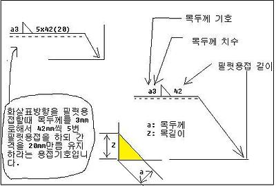
위 그림처럼 a는 목두께를 나타내는 것입니다.
3은 목두께 치수를 나타냅니다.
필릿용접기호가 실선위에 있는 것은 화살표방향에 용접하라는 표시입니다.
용접설계 기호
검색어표시
기재한다. 1.1 기본기호 2. 보조 기호 1.1 기본기호 3. 용접부의 기호 표시방법 3.1 설명선은 용접부를 기호 표시하기 위하여 사용하는 것으로서, 기선, 화살표 및 꼬리로 구성되며, 꼬리는 필요없으면 생략해도...
http://cafe.naver.com/tigweld/5427
KS표준 ㉿ 용접 기호
표준번호 : KSB0052 제정일 : 1967-10-10 최종변경일 : 2007-05-29 제개정여부 : 개정 적용범위 : 이 규격은 제도에서 용접(브레이징 및 솔더링 포함)부의 기호 표시 방법에 대하여 규정한다.
3-1. GENERAL 일반
a. Drawings . 대답 도면.
Drawing or sketching is a universal language used to convey all necessary information to the individual who will fabricate or assemble an object. 도면 또는 스케치 조작하거나 개체를 조립 개별에 대한 모든 필요한 정보를 전달하는 데 사용되는 보편적인 언어입니다. Prints are also used to illustrate how various equipment is operated, maintained, repaired, or lubricated. 지문은 또한 다양한 장비, 운영 방법, 유지, 수리, 또는 윤활 설명하는 데 사용됩니다. The original drawings for prints are made either by directly drawing or tracing a drawing on a translucent tracing paper or cloth using waterproof (India) ink or a special pencil. 지문의 원래 그림을 직접 그리는 또는 반투명 트레이싱 종이 또는 천으로 방수 (인도) 잉크 또는 특수 연필을 사용하여 드로잉을 추적하는 방식으로 만들어진다. The original drawing is referred to as a tracing or master copy. 원래의 그림은 A 또는 추적 마스터 사본이라고합니다.
b. Reproduction Methods . B에 재생 방법.
Various methods of reproduction have been developed which will produce prints of different colors from the master copy. 생식 다양한 방법을 마스터 복사본을 다른 색상의 인쇄물 생산 않습니다 개발되었다.
(1) One of the first processes devised to reproduce a tracing produced white lines on a blue background, hence the term "blueprints". (1) 따라서, 파란색 배경에있는 용어 "청사진"을 생산 추적 화이트 라인을 재현하는 고안 최초의 프로세스 중 하나.
(2) A patented paper identified as "BW" paper produces prints with black lines on a white background. (2) "흑백 처리"종이 생산으로 확인 특허를 종이 흰색 배경에 검은 선으로 인쇄됩니다.
(3) The ammonia process, or "Ozalids", produces prints with either black, blue, or maroon lines on a white background. (3) 암모니아 공정, 또는 "Ozalids"을 생산하는 흰색 배경에 하나, 파랑, 검정 또는 적갈색 라인 출력한다.
(4) Vandyke paper produces a white line on a dark brown background. (4) 반다이 크 작의 신문은 어두운 갈색 바탕에 흰색 라인을 생산하고 있습니다.
(5) Other reproduction methods are the mimeograph machine, ditto machine, and photostatic process. (5) 기타 생식 방법은 등사 기계 저두요 기계 및 photostatic 처리됩니다.
3-2. PARTS OF A DRAWING 그림 부품
a. Title Block . 제목 블록.
The title block contains the drawing number and all the information required to identify the part or assembly represented. 제목 블록 및 도면 번호를 포함하는 부품 또는 어셈블리를 식별하는 데 필요한 모든 정보를 의미합니다. Approved military prints will include the name and address of the Government Agency or organization preparing the drawing, the scale, the drafting record, authentication, and the date. 승인된 군사의 이름과 정부 기관의 주소 또는 조직 드로잉을, 규모의 초안 기록, 인증 준비 및 날짜가 포함됩니다 출력합니다.
b. Revision Block . 개정 차단.
Each drawing has a revision block which is usually located in the upper right corner. 각각의 그림은 보통 오른쪽 상단 모서리에있는 블록을 개정했다. All changes to the drawing are noted in this block. 그림에 대한 모든 변경 사항은이 블록에 설명되어 있습니다. Changes are dated and identified by a number or letter. 변경 날짜가 기입되며 숫자 또는 문자로 식별. If a revision block is not used, a revised drawing may be shown by the addition of a letter to the original number. 개정 블록이 사용되지 않은 경우, 개정된 그림이 원래 번호로 문자의 추가로 게재될 수 있습니다.
c. Drawing Number . 드로잉 번호.
All drawings are identified by a drawing number. 모든 도면은 도면 번호로 식별됩니다. If a print has more than one sheet and each sheet has the same number, this information is included in the number block, indicating the sheet number and the number of sheets in the series. 인쇄 및 하나 이상의 시트가있다면 각각의 시트는 같은 번호를 가지고,이 정보는 시트 번호와 일련의 시트의 개수를 나타내는 숫자 블록에 포함됩니다.
d. Reference Numbers and Dash Numbers . 참조 번호 및 대시 번호.
Reference numbers that appear in the title block refer to other print numbers. 제목 블록에 나타나는 참조 번호가 다른 인쇄 번호를 참조하십시오. When more than one detail is shown on a drawing, dashes and numbers are frequently used. 하나 이상의 세부 사항은 그림에 표시되면, 대시와 숫자가 자주 사용됩니다. If two parts are to be shown in one detail drawing, both prints will have the same drawing number plus a dash and an individual number such as 7873102-1 and 7873102-2. 두 부분으로 한 상세 도면에 표시해야하는 경우, 둘 다 동일한 그리기 번호 플러스 대시와 7873102-1 7873102-2와 같은 개인 전화 번호를 인쇄합니다.
e. Scale . 스케일.
The scale of the print is indicated in one of the spaces within the title block. 인쇄의 규모는 제목 블록 내에있는 공간 중 하나에 표시됩니다. It indicates the size of the drawing as compared with the actual size of the part. 부품의 실제 크기에 비해으로 그것은 그림의 크기를 나타냅니다. Never measure a drawing--use dimensions. 사용 치수 - 절대 드로잉 측정합니다. The print may have been reduced in size from the original drawing. 인쇄는 원래 그림에서 크기가 감소되었을 수도 있습니다.
f. Bill of Material . 재료 빌 f.하십시오. A special block or box on the drawing may contain a list of necessary stock to make an assembly. 특별한 블록이나 상자 그림에서 어셈블리를 만들기 위해 필요한 재고 목록을 포함할 수 있습니다. It also indicates the type of stock, size, and specific amount required. 그것은 또한 재고 있음, 크기 및 필요한 구체적인 금액의 유형을 나타냅니다.
3-3. CONSTRUCTION LINES 라인 건설
a. Full Lines (A, fig. 3-1) . . 3-1) 대답 라인
(전체, 그림. Full lines represent the visible edges or outlines of an object. 전체 라인이 보이는 가장자리를 대표 또는 개체의 설명합니다.

b. Hidden Lines (A, fig. 3-1) . . 3-1) 히든 라인
(숨김, 그림. Hidden lines are made of short dashes which represent hidden edges of an object. 숨겨진 라인 숨겨진 개체의 가장자리를 대표하는 짧은 대시로 이루어져 있습니다.
c. Center Lines (B, fig. 3-1) . 센터 라인
(B 조, 그림. 3-1). Center lines are made with alternating short and long dashes. 센터 라인은 짧고 긴 대시를 교대로 만들어집니다. A line through the center of an object is called a center line. 개체의 센터를 통해 라인은 센터 라인이라고합니다.
d. Cutting Plane Lines (B, fig. 3-1) .절단 계획 라인 (B 조, 그림. 3-1). Cutting plane lines are dashed lines, generally of the same width as the full lines, extending through the area being cut. 절단 평면 라인이 지역되는자를 통해 확장, 전체 라인과 같은 일반적으로 너비의 라인을 점선입니다. Short solid wing lines at each end of the cutting line project at 90 degrees to that line and end in arrowheads which point in the direction of viewing. 보는 방향으로 포인트 화살촉의 그 줄에서 사용과 끝 90 도에서 절단 라인 프로젝트의 각 끝에 짧은 단단한 날개 라인. Capital letters or numerals are placed just beyond the points of the arrows to designate the section. 대문자 혹은 숫자는 섹션을 지정할 화살표의 포인트를 그냥 넘어 게재됩니다.
e. Dimension Lines (A, fig. 3-1) . . 3-1) 치수 라인
(치수, 그림. Dimension lines are fine full lines ending in arrowheads. 차원 라인 화살촉로 끝나는 괜찮 전체 라인이 있습니다. They are used to indicate the measured distance between two points. 그들은 두 지점 사이에서 측정된 거리를 표시하는 데 사용됩니다.
f. Extension Lines (A, fig. 3-1) . . 3-1) 확장 라인
(확장, 그림. Extension lines are fine lines from the outside edges or intermediate points of a drawn object. 확장 라인 바깥 가장자리 또는 그려진 개체의 중간 지점에서 잘 선입니다. They indicate the limits of dimension lines. 그들은 차원 라인의 한계를 나타냅니다.
g. Break Lines (C, fig. 3-1) . 샷 브레이크 라인
(C 조, 그림. 3-1). Break lines are used to show a break in a drawing and are used when it is desired to increase the scale of a drawing of uniform cross section while showing the true size by dimension lines. 브레이크 라인은 그림에서 휴식을 표시하는 데 사용되는 그것은 차원의 라인에 의해 실제 크기를 보여주는 동안 균일한 단면의 그림의 크기를 증가 원하는 경우에 사용됩니다. There are two kinds of break lines: short break and long break. 짧은 휴식 시간과 긴 휴식 : 휴식 라인 두 종류가 있습니다. Short break lines are usually heavy, wavy, semiparallel lines cutting off the object outline across a uniform section. 짧은 휴식 노선, 물결 모양, 유니폼 섹션 전체 개체 개요를 잘라 semiparallel 라인 보통 무거운 있습니다. Long break lines are long dash parallel lines with each long dash in the line connected to the next by a "2" or sharp wave line. 긴 휴식 라인은 오래 "2"또는 날카로운 웨이브 라인으로 다음에 연결된 라인의 각 긴 대시로 병렬 라인을 대시하고 있습니다.
WELD AND WELDING SYMBOLS 용접, 용접 기호
3-4. GENERAL 일반
Welding cannot take its proper place as an engineering tool unless means are provided for conveying the information from the designer to the workmen. 의미는 인부로 디자이너의 정보를 전하는 제공하지 않는 용접 공학 도구로서 적절한 자리를 차지할 수 없습니다. Welding symbols provide the means of placing complete welding information on drawings. 용접 기호는 그림에 대한 완전한 용접 정보를 삽입하는 수단을 제공합니다. The scheme for symbolic representation of welds on engineering drawings used in this manual is consistent with the "third angle" method of projection. 이 설명서에 사용되는 엔지니어링 도면에 용접의 상징적인 표현을위한 제도는 프로젝션의 "세번째 각도"방법과 일치합니다. This is the method predominantly used in the United States. 이것은 주로 미국에서 사용되는 방법입니다.
The joint is the basis of reference for welding symbols. 공동 용접 기호에 대한 참조의 기초입니다. The reference line of the welding symbol (fig. 3-2) is used to designate the type of weld to be made, its location, dimensions, extent, contour, and other supplementary information. 용접 기호 (그림 3-2)의 기준선은, 위치, 크기, 범위, 윤곽 및 기타 보충 정보를 만들 수 용접의 유형을 지정하는 데 사용됩니다. Any welded joint indicated by a symbol will always have an arrow side and an other side. 모든 용접 이음은 항상 화살표 측면과 다른 측면을 갖습니다 기호로 표시. Accordingly, the terms arrow side, other side, and both sides are used herein to locate the weld with respect to the joint. 따라서, 용어 화살표 쪽, 다른쪽에, 그리고 양측은 공동와 관련하여 용접 위치를 여기에 사용됩니다.

The tail of the symbol is used for designating the welding and cutting processes as well as the welding specifications, procedures, or the supplementary information to be used in making the weld. 상징의 꼬리는 용접을 지정하고 용접 제작에 사용되는 프로세스뿐만 아니라 용접 특성, 절차, 또는 보충 정보를 절단하는 데 사용됩니다. If a welder knows the size and type of weld, he has only part of the information necessary for making the weld. 용접기는 용접 크기와 유형을 안다면, 그는 정보를 용접을 만들기위한 필요한 일부만있다. The process, identification of filler metal that is to be used, whether or not peening or root chipping is required, and other pertinent data must be related to the welder. 프로세스가있다 필러 금속의 신분증 또는 피닝 여부 루트가 필요 치핑 및 기타 관련 데이터는 용접기와 관련된해야 사용할 수 있습니다. The notation to be placed in the tail of the symbol indicating these data is to be establish by each user. 표기법은 이러한 데이터는 각 사용자에 의해 설립 예정이다 나타내는 기호의 꼬리에 위치합니다. If notations are not used, the tail of the symbol may be omitted. 표기법을 사용하지 않는 경우, 상징의 꼬리가 생략 수 있습니다.
3-5. ELMENTS OF A WELDING SYMBOL 기호 용접
A distinction is made between the terms "weld symbol" and "welding symbol". 구별은 "용접 기호"와 "용접 기호"를 검색어 사이에 이루어집니다. The weld symbol (fig. 3-3) indicates the desired type of weld. 용접 기호 (그림 3-3) 용접 원하는 유형을 나타냅니다. The welding symbol (fig. 3-2) is a method of representing the weld symbol on drawings. 용접 기호 (그림 3-2) 그림에 용접 기호를 표현하는 방법입니다. The assembled "welding symbol" consists of the following eight elements, or any of these elements as necessary: reference line, arrow, basic weld symbols, dimensions and other data, supplementary symbols, finish symbols, tail, and specification, process, or other reference. 조립 "용접 기호"은 다음과 같은 여덟 요소로 구성되어 또는 필요에 따라 이러한 요소 중 하나 : 참조 선, 화살표, 기본 용접 기호, 치수 및 기타 데이터, 부가 기호, 표면 기호, 꼬리, 그리고 사양, 프로세스, 또는 다른 참조. The locations of welding symbol elements with respect to each other are shown in figure 3-2. 서로 존중과 용접 기호 요소의 위치는 그림 3-2에 표시됩니다.

3-15. FILLET WELDS 필릿 용접
Dimensions of fillet welds must be shown on the same side of the reference line as the weld symbol (A, fig. 3-27). 필릿 용접의 치수는 용접 기호로 기준선 같은 측면에 표시 되어야 합니다 (그림. 3-27).

b. B를 When fillet welds are indicated on both sides of a joint and no general note governing the dimensions of the welds appears on the drawing, the dimensions are indicated as follows: 다음과 같이 필릿 용접은 공동의 양면과 그림에 나타나는 용접의 규격을 규제 없음 일반 메모에 표시됩니다 때, 크기가 표시됩니다 :
(1) When both welds have the same dimensions, one or both may be dimensioned (B or C, fig. 3-27). (1) 두 용접 하나 또는 두 가지 모두가 dimensioned 수 있습니다, 같은 치수를하면 (그림, B 나 C. 3-27).
(2) When the welds differ in dimensions, both must be dimensioned (D, fig. 3-27). (2) 용접이 크기에 차이가하면, 둘 다 (그림, D를. 3-27)을 dimensioned해야합니다.
c. c. When fillet welds are indicated on both sides of a joint and a general note governing the dimensions of the welds appears on the drawing, neither weld need be dimensioned. 필릿 용접은 공동의 양면과 그림에 나타나는 용접의 규격을 관장하는 일반 메모에 표시됩니다 때, 어느 용접은 dimensioned가 필요합니다. However, if the dimensions of one or both welds differ from the dimensions given in the general note, both welds must be dimensioned (C or D, fig. 3-27). 그러나, 하나의 규격 또는 둘 용접은 일반 노트에 주어진 치수와 다를 경우, 두 용접은 (그림, C 또는 D 조. 3-27) dimensioned해야합니다.
3-27. SURFACING WELDS 용접을 부상
a. General . 일반.
(1) The surfacing weld symbol shall be used to indicate surfaces built up by welding (fig. 3-58), whether built up by single-or multiple-pass surfacing welds. 단일 또는 다중 부상 패스 용접에 의해 만들었는지 (1) 부상 용접 기호가 있습니다 (그림 3-58) 용접에 의해 만들어 표면을 표시하는 데 사용하여야한다.

(2) The surfacing weld symbol does not indicate the welding of a joint and thus has no arrow or other side significance. This symbol shall be drawn on the side of the reference line toward the reader and the arrow shall point clearly to the surface on which the weld is to be deposited.
b. Size of Built-up Surfaces . The size (height) of a surface built up by welding shall be indicated by showing the minimum height of the weld deposit to the left of the weld symbol. The dimensions shall always be on the same side of the reference line as the weld symbol (fig. 3-58). When no specific height of weld deposit is desired, no size dimension need be shown on the welding symbol.
c. Extent, Location, and Orientation of Surfaces Built up by Welding . When the entire area of a plane or curved surface is to be built up by welding, no dimension, other than size, need be shown on the welding symbol. If only a portion of the area of a plane or curved surface is to be built up by welding, the extent, location, and orientation of the area to be built up shall be indicated on the drawing.
3-28. FLANGE WELDS
a. General .
(1) The following welding symbols are used for light gage metal joints involving the flaring or flanging of the edges to be joined (fig. 3-59). These symbols have no arrow or other side significance.

(2) Edge flange welds shall be shown by the edge flange weld symbol (A, fig. 3-59).
(3) Corner flange welds shall be shown by the corner flange weld symbol (B, fig. 3-59). In cases where the corner flange joint is not detailed, a break in the arrow is required to show which member is flanged (fig. 3-59).
b. Dimensions of Flange Welds .
(1) Dimensions of flange welds are shown on the same side of the reference line as the weld symbol.
(2) The radius and the height above the point of tangency must be indicated by showing the radius and height, separated by a plus mark, and placed to the left of the weld symbol. The radius and height must read in that order from left to right along the reference line (C, fig. 3-59).
(3) The size (thickness) of flange welds must be shown by a dimension placed outward of the flange dimensions (C, fig. 3-59).
(4) Root opening of flange welds are not shown on the welding symbol. If specification of this dimension is desired, it must be shown on the drawing.
c. Multiple-Joint Flange Welds . For flange welds in which one or more pieces are inserted between the two outer pieces, the same symbol shall be used as for the two outer pieces, regardless of the number of pieces inserted.
3-29. RESISTANCE SPOT WELDS
a. General . Resistance spot weld symbols (fig. 3-3) have no arrow or other side significance in themselves, although supplementary symbols used in con-junction with them may have such significance. Resistance spot weld symbols shall be centered on the reference line. Dimensions may be shown on either side of the reference line.
b. Size of Resistance Spot Welds . Resistance spot welds are dimensioned by either size or strength as follows:
(1) The size of resistance spot welds is designated as the diameter of the weld expressed in fractions or in decimals in hundredths of an inch and must be shown, with or without inch marks, to the left of the weld symbol (>fig. 3-60).

(2) The strength of resistance spot welds is designated as the minimum acceptable shear strength in pounds per spot and must be shown to the left of the weld symbol (fig. 3-61).

c. Spacing of Resistance Spot Welds .
(1) The pitch of resistance spot welds shall be shown to the right of the weld symbol (fig. 3-62).

(2) When the symbols are shown directly on the drawing, the spacing is shown by using dimension lines.
(3) When resistance spot welding extends less than the distance between abrupt changes in the direction of the welding or less than the full length of the joint, the extent must be dimensioned (fig. 3-63).

d. Number of Resistance Spot Welds . When a definite number of welds is desired in a certain joint, the number must be shown in parentheses either above or below the weld symbol (fig. 3-64).

e. Flush Resistance Spot Welding Joints . When the exposed surface of one member of a resistance spot welded joint is to be flush, that surface shall be indicated by adding the flush contour symbol (fig. 3-3) to the weld symbol, (fig. 3-65) in accordance with location specifications given in paragraph 3-7.

3-30. RESISTANCE SEAM WELDS
a. General .
(1) Resistance seam weld symbols have no arrow or other side significance in themselves, although supplementary symbols used in injunction with them may have such significance. Resistance seam weld symbols must be centered on the reference line.
(2) Dimensions of resistance seam welds may be shown on either side of the reference line.
b. Size of Resistance Seam Welds . Resistance seam welds must be dimensioned by either size or strength as follows:
(1) The size of resistance seam welds must be designated as the width of the weld expressed in fractions or in decimals in hundredths of an inch and shall be shown, with or without inch marks, to the left of the weld symbol (fig. 3-66).

(2) The strength of resistance seam welds must be designated as the minimum acceptable shear strength in pounds per linear inch and must be shown to the left of the weld symbol (fig. 3-67).

c. Length of Resistance Seam Welds .
(1) The length of a resistance seam weld, when indicated on the welding symbol, must be shown to the right of the welding symbol (fig. 3-68).

(2) When resistance seam welding extends for the full distance between abrupt changes in the direction of the welding, no length dimension need be shown on the welding symbol.
(3) When resistance seam welding extends less than the distance between abrupt changes in the direction of the welding or less than the full length of the joint, the extent must be dimensioned (fig. 3-69).

d. Pitch of Resistance Seam Welds . The pitch of intermittent resistance seam welding shall be designated as the distance between centers of the weld increments and must be shown to the right of the length dimension (fig. 3-70).

e. Termination of Intermittent Resistance Seam Welding . When intermittent resistance seam welding is used by itself, the symbol indicates that increments are located at the ends of the dimensioned length. When used between continuous resistance seam welding, the symbol indicates that spaces equal to the pitch minus the length of one increment are left at the ends of the dimensional length. Separate symbols must be used for intermittent and continuous resistance seam welding when the two are combined.
f. Flush Projection Welded Joints . When the exposed surface of one member of a projection welded joint is to be made flush, that surface shall be indicated by adding the flush contour symbol (fig. 3-3) to the weld symbol, observing the usual location significance (fig. 3-79).

3-31. PROJECTION WELDS
a. General .
(1) When using projection welding, the spot weld symbol must be used with the projection welding process reference in the tail of the welding symbol. The spot weld symbol must be centered on the reference line.
(2) Embossments on the arrow side member of a joint for projection welding shall be indicated by placing the weld symbol on the side of the reference line toward the reader (fig. 3-72).

(3) Embossment on the other side member of a joint for projection welding shall be indicated by placing the weld symbol on the -side of the reference line away from the reader (fig. 3-73).

(4) Proportions of projections must be shown by a detail or other suitable means.
(5) Dimensions of projection welds must be shown on the same side of the reference line as the weld symbol.
b. Size of Projection Welds .
(1) Projection welds must be dimensioned by strength. Circular projection welds may be dimensioned by size.
(2) The size of circular projection welds shall be designated as the diameter of the weld expressed in fractions or in decimals in hundredths of an inch and shall be shown, with or without inch marks, to the left of the weld symbol (fig. 3-74).

(3) The strength of projection welds shall be designated as the minimum acceptable shear strength in pounds per weld and shall be shown to the left of the weld symbol (fig. 3-75).

c. Spacing of Projection Welds . The pitch of projection welds shall be shown to the right of the weld symbol (fig. 3-76).

d. Number of Projection Welds . When a definite number of projection welds is desired in a certain joint, the number shall be shown in parentheses (F, fig. 3-77).

e. Extent of Projection Welding . When the projection welding extends less than the distance between abrupt changes in the direction of the welding or less than the full length of the joint, the extent shall be dimensioned (fig. 3-78).

f. Flush Resistance Seam Welded Joints . When the exposed surface of one member of a resistance seam welded joint is to be flush, that surface shall be indicated by adding the flush contour symbol (fig. 3-3) to the weld symbol, observing the usual location significance (fig. 3-71).

3-32. FLASH OR UPSET WELDS
a. General . Flash or upset weld symbols have no arrow side or other side significance in themselves, although supplementary symbols used in conjunction with then may have such significance. The weld symbols for flash or upset welding must be centered on the reference line. Dimensions need not be shown on the welding symbol.
b. B를 Surface Contour of Flash or Upset Welds. The contour symbols (fig. 3-3) for flash or upset welds (fig. 3-80) are indicated in the same manner as that for fillet welds (paragraph 3-21).

|