아두이노 드론을 만들어 보자.
--- 부품 리스트 ---
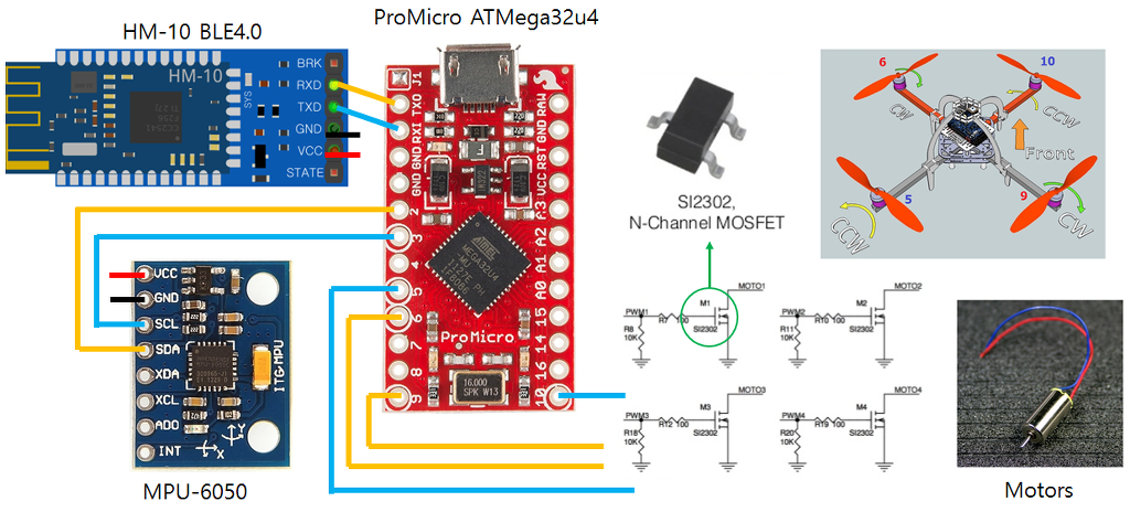
아두이노 ProMicro - ATMega32U4 (Leonardo와 동일한 타입)
MPU-6050 자이로센서
HM-10 블루투스 모듈
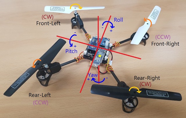
모터 - R20 브러쉬 모터 2xCW(적색,청색) 모터, 2xCCW(검정,백색) 모터
배터리 - BLL 721855 (3.7V 500mAh)
--- 전체 소스코드 ---
 drone_simple_v1.01.zip - 2018-12-02 상보필터 추가, I2C 소스코드 사용
drone_simple_v1.03.zip - 2018-12-05 i2c 대신 Wire.h 사용, 기타 dt 버그 수정
전체 회로도 (클릭하면 이미지를 크게 볼 수 있습니다.)
작성 단계
1. Pro Micro 보드에 EEPROM 읽고 쓰기
2. MPU-6050 자이로 센서 읽기
3. 모터 동작
4. HM-10 블루투스 통신
5. PID 제어
참고 소스:
dron-flight-controller: https://www.firediy.fr/article/mesurer-des-angles-avec-un-arduino-drone-ch-7
RB022_AIRCOPTER_GEAR_TYPE: https://drive.google.com/file/d/0BybAfvqykJsbZjRGdVd6V1hra3c/view
라즈베리파이 드론 키트: https://drive.google.com/file/d/1LpzP1E9xxNxBWgKly9bJGSdY9ndQBETy/view
RB045_M4 드론: https://drive.google.com/file/d/0BybAfvqykJsbUXMtSlprc285RzQ/view
1. Pro Micro 보드에 EEPROM 읽고 쓰기
EEPROM에 구조체의 데이터를 저장하고 불러온다. 이것을 이용하여 드론의 정보를 관리한다.
[실습] 다음 소스를 이해하고, Kp,Ki,Kd 값을 변경하여 쓰고, 읽어서 시리얼모니터에 출력해보자.
#include <avr/eeprom.h>
// ******************************************
// EEPROM에 저장하기 위한 config
// ******************************************
static struct {
float Kp[3], Ki[3], Kd[3];
int16_t angleTrim[3]; // Hovering시 영점 조정 (미세조정)
uint8_t checksum; // MUST BE ON LAST POSITION OF CONF STRUCTURE !
} conf;
uint8_t calculate_sum(uint8_t *cb , uint8_t siz)
{
uint8_t sum=0x55; // checksum init
while(--siz) sum += *cb++; // calculate checksum (without checksum byte)
return sum;
}
// conf 구조체 내용을 eeprom에서 불러온다.
void readEEPROM()
{
uint8_t i; eeprom_read_block((void*)&conf, (void*)0, sizeof(conf));
// 저장된 내용이 데이터가 깨졌을 경우 초기 값으로 대체
if(calculate_sum((uint8_t*)&conf, sizeof(conf)) != conf.checksum) {
blinkLED(6,100,3);
LoadDefaults();
writeEEPROM(); // 초기화 하여 저장한다.
}
}
// conf 구조체 내용을 eeprom에 저장한다.
void writeEEPROM()
{
conf.checksum = calculate_sum((uint8_t*)&conf, sizeof(conf));
eeprom_write_block((const void*)&conf, (void*)0, sizeof(conf));
//readEEPROM();
blinkLED(15,20,1);
} |
2. MPU-6050 자이로 센서 읽기
- 아두이노 Serial1 을 사용하여 read()함수로 데이터를 읽어 처리할때 드론이 뜨지 못한다. 직접 i2c 함수로 접근하는게 더 빠름.
- angle 각도 (pitch, roll, yaw)를 이용하여 PID 제어를 할 경우 드론이 휘청 거린다. 자이로와 가속도의 누적 데이터로 인한 반응이 떨어져서 생기는 현상
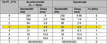
- 레지스터 설정에서 자이로센서는 LPF (DLPF_CFG)로 설정해야 오차를 줄일 수 있다.
[실습] 다음 소스를 이용하여 다음 정보를 시리얼모니터로 출력하시오.
가속도센서(accelation) 원시 데이터 (acc_raw)과 자이로센서(gyrometer) 원시 데이터 (gyro_raw)
Roll, Pitch, Yaw 각도
PWR_MGMT_1 레지스터 (0x6B)

CONFIG 레지스터 (0x1A)

GYRO_CONFIG 레지스터 (0x1B)


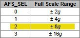
ACCEL_CONFIG 레지스터 (0x1C)

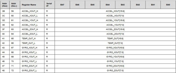
MPU6050 레지스터 map
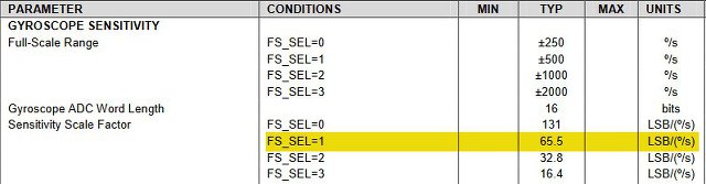
Sensitivity Scale Factor gyroscop:
65.5는 각속도를 의미하며, 최대 500도/sec의 범위를 갖는다. 즉, -32768~32767 범위의 값은 - 500~500 도/sec로 표현된다.
1 도/sec = 32768 / 500 = 65.5
2 도/sec = 32768 / 500 * 2 = 131
500도/sec = 32768 / 500 * 500 = 32768
* Wire.h를 이용한 MPU-6050 제어 코드
#include <Wire.h>
#define MPU6050_ADDRESS 0x68 // address pin AD0 low (GND), default for FreeIMU v0.4 and InvenSense board
#define ACC_1G 256 // this is the 1G measured acceleration #define ACC_2G 512 // ACCEL_CONFIG -- AFS_SEL= 0 (Full Scale = +/-2G)
#define ACC_4G 1024 // ACCEL_CONFIG -- AFS_SEL= 0 (Full Scale = +/-4G)
#define ACC_8G 4096 // ACCEL_CONFIG -- AFS_SEL= 2 (Full Scale = +/-8G)
#define GYRO_SSF 16.4 // Sensitivity Scale Factor of the gyro from datasheet
// GYRO_CONFIG -- FS_SEL = 3: Full scale set to 2000 deg/sec enum xyz { X, Y, Z };
enum rc { ROLL, PITCH, YAW, THROTTLE, AUX1, AUX2, AUX3, AUX4 };
uint8_t rawADC[14];
int16_t gyro_raw[3] = {0,0,0}; // Gyroscope(자이로스코프) 원시 데이터
int16_t gyro_zero[3] = {0,0,0}; // 영점 보정값
float gyro_angle[3] = {0,0,0}; // 자이로센서값 int16_t acc_raw[3] = {0,0,0}; // Accelerometer(가속계) 원시 데이터
int16_t acc_zero[3] = {0,0,0}; // 영점 보정값
float acc_angle[3] = {0,0,0}; // 절대각도 [-180:180]
// ***************************************************************************************
// MPU6050 - Gyroscope and Accelerometer
// ***************************************************************************************
void initMPU6050()
{
Wire.begin();
TWBR = ((F_CPU / 400000L) - 16) / 2; //24 또는 // 400kHz I2C clock (200kHz if CPU is 8MHz) // Configure power management
Wire.beginTransmission(MPU6050_ADDRESS); // Start communication with MPU
Wire.write(0x6B); // Request the PWR_MGMT_1 register
Wire.write(0x80); // DEVICE_RESET = 1
Wire.endTransmission(); // End the transmission
delay(5);
//Configure power management: PWR_MGMT_1
Wire.beginTransmission(MPU6050_ADDRESS); // Start communication with MPU
Wire.write(0x6B); // Request the PWR_MGMT_1 register
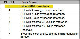
Wire.write(0x03); // SLEEP=0; CYCLE 0; TEMP_DIS=0; CLKSEL=3; PLL with Z gyro ref
Wire.endTransmission(); // End the transmission
// Configure the gyro's sensitivity
Wire.beginTransmission(MPU6050_ADDRESS); // Start communication with MPU
Wire.write(0x1B); // Request the GYRO_CONFIG register
Wire.write(0x18); // FS_SEL = 2; Full Scale Range is ±500°/s
Wire.endTransmission(); // End the transmission
// Configure the acceleromter's sensitivity
Wire.beginTransmission(MPU6050_ADDRESS); // Start communication with MPU
Wire.write(0x1C); // Request the ACCEL_CONFIG register
Wire.write(0x10); // AFS_SEL = 2; Full Scale Range is ±8g
Wire.endTransmission(); // End the transmission
// Configure low pass filter
Wire.beginTransmission(MPU6050_ADDRESS); // Start communication with MPU
Wire.write(0x1A); // Request the CONFIG register
Wire.write(0x02); // DLPF(Digital Low Pass Filter) is about 94Hz(acc), 98Hz(gyro)
Wire.endTransmission(); // End the transmission
}
// ***************************************************************************************
// raw 데이터 얻기
// ***************************************************************************************
void getMPU6050()
{
uint32_t temp;
Wire.beginTransmission(MPU6050_ADDRESS); // Start communicating with the MPU-6050
Wire.write(0x3B); // Send the requested starting register
Wire.endTransmission(); // End the transmission
Wire.requestFrom(MPU6050_ADDRESS,14); // Request 14 bytes from the MPU-6050
while(Wire.available() < 14); // Wait until all the bytes are received
acc_raw[X] = Wire.read() << 8 | Wire.read();
acc_raw[Y] = Wire.read() << 8 | Wire.read();
acc_raw[Z] = Wire.read() << 8 | Wire.read();
temp = Wire.read() << 8 | Wire.read();
gyro_raw[X] = (Wire.read() << 8 | Wire.read()) >>2; // 자이로센서 노이즈를 제거하기 위해
gyro_raw[Y] = (Wire.read() << 8 | Wire.read()) >> 2;
gyro_raw[Z] = (Wire.read() << 8 | Wire.read()) >> 2;
}
// Calibration
// ***************************************************************************************
void calibMPU6050()
{
int32_t acc_sum[3]={0,0,0}, gyro_sum[3]={0,0,0}, i, repeat = 1000;
uint8_t axis;
for(i=0;i<repeat;i++) {
getMPU6050(); // 가속도와 자이로센서 읽기
delay(2);
// 합계 구하기
for (axis = 0; axis < 3; axis++) {
acc_sum[axis] += acc_raw[axis];
gyro_sum[axis] += gyro_raw[axis];
}
}
// 평균값 구하기
for (axis = 0; axis < 3; axis++) {
acc_zero[axis] = acc_sum[axis] / repeat;
gyro_zero[axis] = gyro_sum[axis] / repeat;
}
acc_zero[YAW] -= ACC_8G; // ACCEL_CONFIG -- AFS_SEL= 2 (Full Scale = +/-8G)
}
// ***************************************************************************************
// IMU(Inertial Measurement Unit) 관성측정장치
// ***************************************************************************************
void computeMPU6050()
{
uint8_t axis;
// calculate time
uint32_t time_now = millis();
dt = (double)(time_now - time_prev) / 1000.0;
time_prev = time_now;
getMPU6050(); // 가속도, 자이로센서 값 읽기
// 영점 조정하기
for (axis = 0; axis < 3; axis++) {
acc_raw[axis] -= acc_zero[axis] ;
gyro_raw[axis] -= gyro_zero[axis];
}
// Calculate total 3D acceleration vector : √(X² + Y² + Z²)
acc_mag = sqrt(pow(acc_raw[X], 2) + pow(acc_raw[Y], 2) + pow(acc_raw[Z], 2)); // To prevent asin to produce a NaN, make sure the input value is within [-1;+1]
if (abs(acc_raw[X]) < acc_mag) acc_angle[X] = asin((float)acc_raw[Y] / acc_mag) * (180 / PI);
if (abs(acc_raw[Y]) < acc_mag) acc_angle[Y] = asin((float)acc_raw[X] / acc_mag) * (180 / PI);
// Calculate gyro angle
for (axis=0;axis<3;axis++) gyro_angle[axis] = gyro_raw[axis] / SSF_GYRO; // 상보필터 (각도를 구하기 위해 dt를 곱하고, 4를 다시 곱해 원래의 raw값으로 복원)
angle_comp[PITCH] = 0.93 * (angle_comp[PITCH] + gyro_angle[PITCH] * 4 * dt ) + 0.07 * acc_angle[PITCH];
angle_comp[ROLL] = 0.93 * (angle_comp[ROLL] + gyro_angle[ROLL] * 4 * dt ) + 0.07 * acc_angle[ROLL];
angle_comp[YAW] -= gyro_angle[YAW] * 4 * dt;
}
void setup() {
Serial.begin(115200); // USB 시리얼모니터 initMPU6050(); // 자이로센서 설정
}
void loop() {
computeMPU6050(); // Roll,Pitch,Yaw 계산
} |
* I2C 통신 모듈 사용할 경우 추가 코드 부분 (다음은 위 소스와 다른 부분만 보여준다.)
#define I2C_SPEED 400000L //400kHz fast mode, it works only with some WMP clones
#define I2C_WRITE_MODE 0
#define I2C_READ_MODE 1
#define I2C_PULLUPS_ENABLE PORTD |= 1<<0; PORTD |= 1<<1; // PIN 2&3 (SDA&SCL)
#define I2C_PULLUPS_DISABLE PORTD &= ~(1<<0); PORTD &= ~(1<<1);
// ***************************************************************************************
// MPU6050 - Gyroscope and Accelerometer
// ***************************************************************************************
void initMPU6050()
{ i2c_init(); // I2C 통신 for MPU6050
TWBR = ((F_CPU / 400000L) - 16) / 2; // change the I2C clock rate to 400kHz
delay(100);
i2c_writeReg(MPU6050_ADDRESS, 0x6B, 0x80); //PWR_MGMT_1 -- DEVICE_RESET 1
delay(5);
// USB 전원을 사용할때는 모터가 동작 안한다.
//PWR_MGMT_1 -- SLEEP 0; CYCLE 0; TEMP_DIS 0; CLKSEL 3 (PLL with Z Gyro reference) i2c_writeReg(MPU6050_ADDRESS, 0x6B, 0x03);
// LPF 필터를 사용한다.
//CONFIG -- EXT_SYNC_SET 0 (disable input pin for data sync) ; // default DLPF_CFG = 0 => ACC bandwidth = 260Hz GYRO bandwidth = 256Hz) i2c_writeReg(MPU6050_ADDRESS, 0x1A, MPU6050_DLPF_CFG); //GYRO_CONFIG -- FS_SEL = 3: Full scale set to 2000 deg/sec
i2c_writeReg(MPU6050_ADDRESS, 0x1B, 0x18);
//ACCEL_CONFIG -- AFS_SEL=2 (Full Scale = +/-8G) ; ACCELL_HPF=0
i2c_writeReg(MPU6050_ADDRESS, 0x1C, 0x10);
calibMPU6050();
time_prev = millis(); }
// ***************************************************************************************
// raw 데이터 얻기
// ***************************************************************************************
void getMPU6050()
{
i2c_read_reg_to_buf(MPU6050_ADDRESS, 0x43, &rawADC, 14); // 아두이노 코드보다 속도 개선
acc_raw[X] = (rawADC[0]<<8) | rawADC[1];
acc_raw[Y] = (rawADC[2]<<8) | rawADC[3];
acc_raw[Z] = (rawADC[4]<<8) | rawADC[5];
gyro_raw[X] = ( ((rawADC[8]<<8) | rawADC[9]) >> 2 ); // 노이즈를 줄이기. 노이즈로 잘 뜨지 않는 현상이 있다.
gyro_raw[Y] = ( ((rawADC[10]<<8) | rawADC[11]) >> 2 );
gyro_raw[Z] = -( ((rawADC[12]<<8) | rawADC[13]) >> 2 );
}
// ***************************************************************************************
// I2C communication functions
// ***************************************************************************************
void i2c_init(void)
{
I2C_PULLUPS_DISABLE
TWSR = 0; // no prescaler => prescaler = 1
TWBR = ((F_CPU / I2C_SPEED) - 16) / 2; // change the I2C clock rate
TWCR = 1<<TWEN; // enable twi module, no interrupt
}
void i2c_beginTransmission(uint8_t address,int mode)
{
TWCR = (1<<TWINT) | (1<<TWSTA) | (1<<TWEN); // send REPEAT START condition
waitTransmissionI2C(); // wait until transmission completed
TWDR = address<<1 | mode; // send device address
TWCR = (1<<TWINT) | (1<<TWEN);
waitTransmissionI2C(); // wail until transmission completed
}
void i2c_endTransmission(void)
{
TWCR = (1<<TWINT) | (1<<TWSTO) | (1<<TWEN); // send STOP condition
// while(TWCR & (1<<TWSTO)); // <- can produce a blocking state with some WMP clones
} void i2c_write(uint8_t data)
{
TWDR = data; // send data to the previously addressed device
TWCR = (1<<TWINT) | (1<<TWEN);
waitTransmissionI2C();
} uint8_t i2c_read(uint8_t ack)
{
TWCR = (1<<TWINT) | (1<<TWEN) | (ack? (1<<TWEA) : 0);
waitTransmissionI2C();
uint8_t r = TWDR;
if (!ack) i2c_endTransmission();
return r;
} uint8_t i2c_readAck() { return i2c_read(1); }
uint8_t i2c_readNak(void) { return i2c_read(0); }
void waitTransmissionI2C()
{
uint16_t count = 255;
while (!(TWCR & (1<<TWINT))) {
count--;
if (count==0) { //we are in a blocking state => we don't insist
TWCR = 0; //and we force a reset on TWINT register
break;
}
}
}
size_t i2c_read_to_buf(uint8_t add, void *buf, size_t size)
{
i2c_beginTransmission(add, I2C_READ_MODE); // I2C read direction
size_t bytes_read = 0;
uint8_t *b = (uint8_t*)buf;
while (size--) {
/* acknowledge all but the final byte */
*b++ = i2c_read(size > 0);
/* TODO catch I2C errors here and abort */
bytes_read++;
}
return bytes_read;
}
size_t i2c_read_reg_to_buf(uint8_t add, uint8_t reg, void *buf, size_t size)
{
i2c_beginTransmission(add, I2C_WRITE_MODE); // I2C write direction
i2c_write(reg); // register selection
return i2c_read_to_buf(add, buf, size);
}
/* transform a series of bytes from big endian to little endian and vice versa. */
void swap_endianness(void *buf, size_t size)
{
uint8_t tray;
uint8_t *from;
uint8_t *to;
/* keep swapping until the pointers have assed each other */
for (from = (uint8_t*)buf, to = &from[size-1]; from < to; from++, to--) {
tray = *from;
*from = *to;
*to = tray;
}
}
void i2c_writeReg(uint8_t add, uint8_t reg, uint8_t val)
{
i2c_beginTransmission(add, I2C_WRITE_MODE); // I2C write direction
i2c_write(reg); // register selection
i2c_write(val); // value to write in register
i2c_endTransmission();
}
|
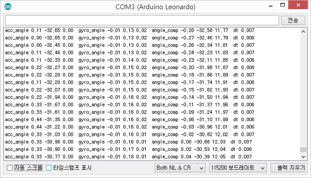
시리얼모니터를 통해 pitch, roll, yaw의 각도를 정확히 살펴본다.
3. 모터 동작
[실습] 다음 소스를 이용하여 시리얼모니터에서 1~4번 번호를 입력하면 한개의 모터가 최소값에서 최대값으로 동작하도록 한다.
즉, 각각 하나씩 모터 속도를 증가시켜 보자.
Realacc R20 RC 쿼드콥터 - 검정색 백색 (CCW) 적색 청색 (CW)

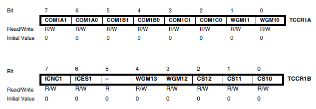
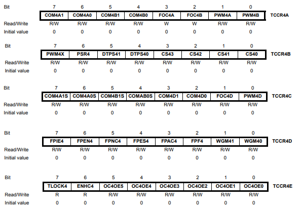
모터구동을 위한 PWM 설정 (참고:Timer/Counter 4 with PWM)
#include <Wire.h>
/*************** Motor THROTTLE for ESC (Electronic Speed Controller) **************/
#define MIN_THROTTLE 1000
#define MAX_THROTTLE 2000
#define MIN_CHECK 1100
#define MAX_CHECK 1900
/*****************************************************************************************
4개의 모터를 조작한다. 범위는 [1000:2000] -> [8000:16000] 또는 [1000:2000]
Timer 1A & 1B와 Timer 4A & 4D 네개를 사용하여 PWM 신호를 제어한다.
*****************************************************************************************/ #define NUMBER_MOTOR 4
int16_t motor[NUMBER_MOTOR] = { 0,0,0,0 }; // 모터 구동을 위한 PWM 값
uint8_t PWM_PIN[NUMBER_MOTOR] = {9,10,5,6}; // REAR_R FRONT_R REAR_L FRONT_L /* to calibrate all ESCs connected to MWii at the same time (useful to avoid unplugging/re-plugging each ESC)
Read How To at http://code.google.com/p/multiwii/wiki/ESCsCalibration */
#define MINCOMMAND -1056 // Disarm 일때의 ESC의 값
#define ESC_CALIB_LOW MINCOMMAND // ESCs calibration을 위한 모터의 최소값
#define ESC_CALIB_HIGH 2000 // ESCs calibration을 위한 모터의 최대값
// rc (Remote Control) functions
enum rc { ROLL, PITCH, YAW, THROTTLE, AUX1, AUX2, AUX3, AUX4 }; // 입력받은 조작키 값을 재조정한 최종 명령값, [-500;+500] for ROLL/PITCH/YAW- ESC, [1000;2000] for THROTTLE
float rcCommand[4] = {0,0,0,0}; int16_t axisPID[3] = {0,0,0};
/*************************************************************************************
Initialize the PWM Timers and Registers
*************************************************************************************/
void initMotor()
{
// Mark all PWM pins as Output
for(uint8_t i=0;i<NUMBER_MOTOR;i++) pinMode(PWM_PIN[i],OUTPUT);
// Specific PWM Timers & Registers for the atmega32u4 (Promicro)
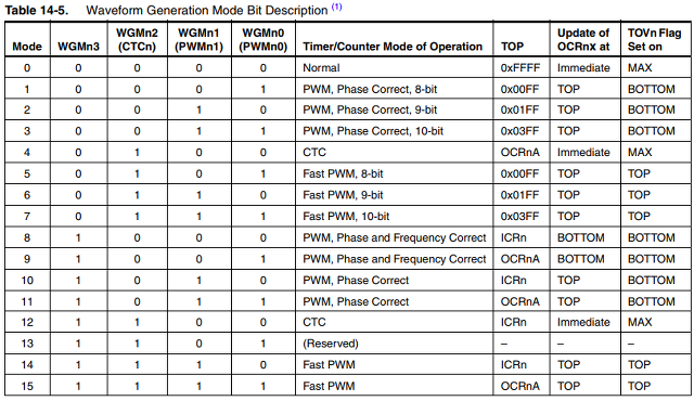
TCCR1A |= (1<<WGM11); // phase correct mode & no prescaler
TCCR1A &= ~(1<<WGM10);
TCCR1B &= ~(1<<WGM12) & ~(1<<CS11) & ~(1<<CS12);
TCCR1B |= (1<<WGM13) | (1<<CS10);
ICR1 |= 0x3FFF; // TOP to 16383;
TCCR1A |= _BV(COM1A1); // connect pin 9 to timer 1 channel A
TCCR1A |= _BV(COM1B1); // connect pin 10 to timer 1 channel B
TCCR4E |= (1<<ENHC4); // enhanced pwm mode
TCCR4B &= ~(1<<CS41); TCCR4B |= (1<<CS42)|(1<<CS40); // prescaler to 16
TCCR4D |= (1<<WGM40);
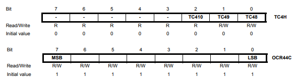
TC4H = 0x7;
OCR4C = 0xFF; // phase and frequency correct mode & top to 1023 but with enhanced pwm mode we have 2047
TCCR4A |= (1<<COM4A0)|(1<<PWM4A); // connect pin 5 to timer 4 channel A
TCCR4C |= (1<<COM4D1)|(1<<PWM4D); // connect pin 6 to timer 4 channel D
/******** special version of MultiWii to calibrate all attached ESCs ************/
/*
writeAllMotors(ESC_CALIB_HIGH);
delay(3000);
writeAllMotors(ESC_CALIB_LOW);
delay(500);
while (1) {
delay(5000);
blinkLED(2,20, 2);
}
exit; // statement never reached
*/
writeAllMotors(MINCOMMAND);
delay(300);
}
/*************************************************************************************
Writes the Motors values to the PWM compare register
*************************************************************************************/
void writeMotors() // [1000;2000] => [125;250]
{
int16_t maxMotor,i;
// -----------------------------------------------------------------------
// apply to motors
motor[0] = rcCommand[THROTTLE] - axisPID[ROLL] + axisPID[PITCH] - axisPID[YAW]; //REAR_R
motor[1] = rcCommand[THROTTLE] - axisPID[ROLL] - axisPID[PITCH] + axisPID[YAW]; //FRONT_R
motor[2] = rcCommand[THROTTLE] + axisPID[ROLL] + axisPID[PITCH] + axisPID[YAW]; //REAR_L
motor[3] = rcCommand[THROTTLE] + axisPID[ROLL] - axisPID[PITCH] - axisPID[YAW]; //FRONT_L
// -----------------------------------------------------------------------
// normalize the Motors values
for(i=0; i< NUMBER_MOTOR; i++) if (motor[i]>maxMotor) maxMotor=motor[i];
for(i=0; i< NUMBER_MOTOR; i++) {
// 하나의 모터가 최대치를 초과할때, 전체 모터를 초과 크기만큼 전부 내린다.
if (maxMotor > MAX_THROTTLE) motor[i] -= maxMotor - MAX_THROTTLE;
motor[i] = constrain(motor[i], MIN_THROTTLE, MAX_THROTTLE);
// 착륙시 또는 dis-armed 이면 모터를 정지한다.
// if (rcData[THROTTLE] < MIN_CHECK || !fARMED) motor[i] = MINCOMMAND; // 모터테스트를 위해 주석처리
}
// -----------------------------------------------------------------------
// Specific PWM Timers & Registers for the atmega32u4 (Promicro)
// Timer 1 A [1000:2000] => [8000:16000]
OCR1A = ((motor[0]<<4) - 16000) + 128; // REAR_R (pin 9)
// Timer 1 B [1000:2000] => [8000:16000]
OCR1B = ((motor[1]<<4) - 16000) + 128; // FRONT_R (pin 10)
// Timer 4 A [1000:2000] => [1000:2000], 16bit 데이터, 2047 값일때 모터가 정지한다.
TC4H = 2047-(((motor[2]-1000)<<1)+16)>>8;
OCR4A = (2047-(((motor[2]-1000)<<1)+16)&0xFF); // REAR_L (pin 5)
// Timer 4 D [1000:2000] => [1000:2000], 16bit 데이터, 0 값일때 모터가 정지한다.
TC4H = (((motor[3]-1000)<<1)+16)>>8;
OCR4D = ((((motor[3]-1000)<<1)+16)&0xFF); // FRONT_L (pin 6)
} /*************************************************************************************
모든 모터를 동작 시킨다.
*************************************************************************************/
void writeAllMotors(int16_t mc) // Sends commands to all motors
{
for (uint8_t i =0;i<NUMBER_MOTOR;i++) motor[i]=mc;
writeMotors();
} /*************************************************************************************
모터 4개를 순차적으로 속도를 올려보며 테스트한다.
*************************************************************************************/
void testMotors()
{
for(int i=0;i<8;i++) {
writeAllMotors(MIN_THROTTLE+100*i);
delay(1000);
}
writeAllMotors(MIN_THROTTLE); // stop
delay(1000);
} |
4. HM-10 자동 설정
- 공장 초기화 된 경우 HM-10은 다음과 같은 소스를 이용해 현재 시스템에 맞게 초기화할 필요가 있다.
- 다음 소스 중 resetHM10() 함수를 Setup() 함수내에 한번만 실행하면 된다.
// -----------------------------------------------------------
// HM-10 자동설정하기
// -----------------------------------------------------------
//#include <SoftwareSerial.h> // 명령어를 보내고 Response를 받는다.
void sendCmd(char* cmd)
{
Serial1.write(cmd);
Serial.print(cmd);
Serial.print("-->");
delay(400);
while (Serial1.available()) { Serial.write(Serial1.read()); }
Serial.println();
} void resetHM10()
{
long baud[8]={ 4800, 9600, 14400, 19200, 28800, 38400, 57600, 115200 };
Serial.begin(115200); // USB 시리얼모니터
delay(2000);
// 여러 종류의 baud를 설정하여 맞는 속도를 찾는다.
Serial.println("Search baud rate: Send AT, wait for OK");
for(int i=1;i<8;i++) {
Serial.print("Baud :"); Serial.println(baud[i]);
Serial1.begin( baud[i] ); delay(500);
// AT 명령어를 2번 정도 보낸다. 간혹 기존에 명령어가 잘못 들어간 경우가 있음.
Serial1.print("AT\r\n"); delay(100);
Serial1.print("AT"); delay(100); // 지연시간은 꼭 필요하다. char str[100];
int nStr = 0;
while(Serial1.available()) {
str[nStr++] = Serial1.read(); // OK 문자를 받는다.
}
Serial.println(str);
if(strncmp(str,"OK",2)==0) {
// HM-10 상태를 자동 설정하기
Serial.println("\nStatus of HM10 ----------------");
sendCmd("AT+NAMEAIR123");
sendCmd("AT+PASS000000");
sendCmd("AT+BAUD4"); // 0: 9600, 1: 19200, 2: 38400, 3: 57600, 4: 115200
sendCmd("AT+TYPE0"); // 0: 모듈 bond 모드: Not need PIN Code
sendCmd("AT+MODE2"); // 2: Remote Control Mode + Trasmission Mode
sendCmd("AT+ROLE0"); // 0: Peripheral (=Slave), 1: Central (=Master)
sendCmd("AT+ADTY0"); // 0: Advertising ScanResponse, Connectable 불루투스 페어링 모드
break;
}
else {
Serial.print("Not found in ");
Serial.print(baud[i]);
Serial.println(" baud");
}
}
// 상태 확인 sendCmd("AT+NAME?");
sendCmd("AT+PASS?");
sendCmd("AT+BAUD?");
sendCmd("AT+TYPE?");
sendCmd("AT+MODE?");
sendCmd("AT+ROLE?");
sendCmd("AT+ADTY?");
Serial.println("Finished setup HM10, please remove resetHM10() in source code!");
while(1);
} |
5. HM-10 블루투스 통신
[실습] 다음 소스를 이용하여 컨트롤 앱에서 전송하는 데이터를 받아보자. 데이터는 rcCommand이며, Roll, Pitch, Yaw, Throttle 정보를 갖고 있다.
다두이노 드론 앱을 다운받아 설치한다.
(1) 오른쪽 상단을 누르면 bluetooth를 연결할 수 있다.
(2) 연결이 성공한 후, 다음 화면에서 아래쪽 UNLOCK를 누르면 Arm 모드가 되어 동작이 가능하다.

위 드론 제어판에서 보내는 프로토콜은 다음과 같다. 데이터 영역에는 Roll, Pitch, Yaw, Throttle 등의 조작 명령을 포함한다.
request: $M< [크기] [명령어] [...데이터...] [CRC]
response: $M> [크기] [명령어] [...데이터...] [CRC] |
블루투스 HM-10 이 serial에 연결되어 있다.
/*****************************************************************************************
Serial - 통신연결, 프로토콜 송/수신으로 각종 명령을 수행한다.
*****************************************************************************************/
#define RC_CHANS 8 // rc chain 개수 /******************************* 송수신 명령어 *************************************/
#define MSP_GET_RAW_IMU 102 // IMU 데이터 얻기 9 DOF
#define MSP_GET_MOTOR 104 // 8 motors
#define MSP_GET_RCDATA 105 // 기존 rcData 얻기
#define MSP_GET_PID 112 // PID coeff (9 are used currently) #define MSP_TRIM_UP 153 // 영점 조정
#define MSP_TRIM_DOWN 154
#define MSP_TRIM_LEFT 155
#define MSP_TRIM_RIGHT 156 #define MSP_SET_RCDATA 150 // 리모콘에서 보낸 데이터를 rcData에 설정하기
#define MSP_SET_ARM 151 // ARM 설정 (모터 동작 가능)
#define MSP_SET_DISARM 152 // Dis-arm 설정 (모터 동작 해제)
#define MSP_SET_PID 202 // PID coeff (9 are used currently)
#define MSP_SET_ACC_CALIB 205 // acceleration calibration
/*************** Motor THROTTLE for ESC (Electronic Speed Controller) **************/
#define MIN_THROTTLE 1000
#define MAX_THROTTLE 2000
#define MIN_CHECK 1100
#define MAX_CHECK 1900
// 통신 및 송수신 버퍼
#define RX_BUFFER_SIZE 128
#define TX_BUFFER_SIZE 128 uint8_t BuffTX[TX_BUFFER_SIZE]; // 전송 버퍼
uint8_t idxHeadTX, idxTailTX; // 전송 버퍼 머리와 꼬리 index 번호
uint8_t BuffRX[RX_BUFFER_SIZE]; // 입력 버퍼
uint8_t idxBuffRX; // 입력 버퍼 index 번호
uint8_t checksum; // 체크 섬
uint8_t cmdMSP; // 입력 프로토콜 중 command (명령어 코드)
static enum _serial_state { // 프로토콜 구조
IDLE,
HEADER_START,
HEADER_M,
HEADER_ARROW,
HEADER_SIZE,
HEADER_CMD,
} c_state;
// Bluetooth 통신을 통해 조작키로부터 입력받은 값. interval [1000;2000]
int16_t rcData[RC_CHANS] = {1500, 1500, 1500, 1500, 1500, 1500, 1500, 1500}; // 조작키의 입력값을 재조정한 최종 명령값, [-500;+500] for ROLL/PITCH/YAW- ESC, [1000;2000] for THROTTLE
float rcCommand[4] = {0,0,0,0};
// *************************************************************************************************
// 통신 프로토콜을 해석하여 해당 명령을 수행(evaluateCommand()) 하고 결과(response)를 보내는 함수
// 기본 패킷: request: $M< [크기] [명령어] [...데이터...] [CRC]
// response: $M> [크기] [명령어] [...데이터...] [CRC]
// ************************************************************************************************* void serialComm()
{
uint8_t c;
static uint8_t offset;
static uint8_t dataSize; while (Serial1.available()) {
c = Serial1.read();
// if(ch=='$') Serial.println(); Serial.print(c); Serial.print(") ");
// regular data handling to detect and handle MSP and other data
if (c_state == IDLE) {
c_state = (c=='$') ? HEADER_START : IDLE;
// ---------------------------------------------------------
if (c_state == IDLE) evaluateOtherData(c); // evaluate all other incoming serial data
// ---------------------------------------------------------
} else if (c_state == HEADER_START) {
c_state = (c=='M') ? HEADER_M : IDLE;
} else if (c_state == HEADER_M) {
c_state = (c=='<') ? HEADER_ARROW : IDLE;
} else if (c_state == HEADER_ARROW) {
// now we are expecting the payload size
if (c > RX_BUFFER_SIZE) { c_state = IDLE; continue; }
dataSize = c;
offset = 0;
checksum = 0;
idxBuffRX = 0;
checksum ^= c; // calc checksum
c_state = HEADER_SIZE;
} else if (c_state == HEADER_SIZE) {
cmdMSP = c;
checksum ^= c;
c_state = HEADER_CMD;
} else if (c_state == HEADER_CMD && offset < dataSize) {
checksum ^= c;
BuffRX[offset++] = c;
}
// compare calculated and transferred checksum
else if (c_state == HEADER_CMD && offset >= dataSize) {
// ---------------------------------------------------------
if (checksum == c) evaluateCommand(cmdMSP); // we got a valid packet, evaluate it
// ---------------------------------------------------------
c_state = IDLE;
}
}
} // *************************************************************************************************
// 프로토콜 명령 코드에 따른 기능 수행
// *************************************************************************************************
void evaluateCommand(uint8_t cmd_msp)
{
unsigned char auxChannels;
uint16_t val; switch(cmd_msp) {
case MSP_SET_RCDATA:
for(uint8_t i = 0;i < 4;i++) {
val = read8();
rcData[i] = 1000 + val * 4; // 범위 [1000:2000]
}
auxChannels = read8();
for(uint8_t i=0;i<4;i++) {
val = (auxChannels >> ((3-i)*2)) & 0x03;
rcData[4+i] = 1000 + (val * 500);
}
break;
case MSP_SET_ARM:
//go_Arm(true);
serialize_head(0, 0);
serialize8(checksum);
UartSendData();
break;
case MSP_SET_DISARM:
//go_Arm(false);
serialize_head(0, 0);
serialize8(checksum);
UartSendData();
break;
default: // we do not know how to handle the (valid) message, indicate error MSP $M!
Serial.println("Error in evaluateCommand()");
serialize_head(1, 0); // error response
serialize8(checksum);
UartSendData();
break;
}
}
// evaluate all other incoming serial data
void evaluateOtherData(uint8_t sr)
{
switch (sr) {
case 's':
case 'S':
//if (!fARMED) configurationLoop();
break;
}
} // *******************************************************
// 전송할 프로토콜 작성
// *******************************************************
void serialize_head(uint8_t err, uint8_t s)
{
serialize8('$');
serialize8('M');
serialize8(err ? '!' : '>');
checksum = 0; // start calculating a new checksum
serialize8(s); // size
serialize8(cmdMSP); // command code
}
void serialize16(int16_t a) { serialize8((a ) & 0xFF); serialize8((a>>8) & 0xFF); }
void serialize8(uint8_t a)
{
uint8_t t = idxHeadTX;
if (++t >= TX_BUFFER_SIZE) t = 0;
BuffTX[t] = a;
checksum ^= a;
idxHeadTX = t;
}
void UartSendData()
{
while(idxHeadTX != idxTailTX) {
if (++idxTailTX >= TX_BUFFER_SIZE) idxTailTX = 0;
Serial1.write( (unsigned char)BuffTX[ idxTailTX ] );
}
} // 버퍼에서 수신된 데이터 읽어오기
uint8_t read8() { return BuffRX[ idxBuffRX++ ] & 0xff; }
void setup()
{
Serial.begin(9600); // USB 시리얼모니터
Serial1.begin(115200); // Bluetooth 시리얼통신
}
void loop()
{
serialComm();
} |
6. PID 제어
PID 값은 Kp=1.94, Ki=0.0037, Kd=0.36 으로 설정하여 테스트 한다. 다음 소스에서 anglrTrim은 영점조정을 위한 값으로 기본값은 0이다.
주의: 4개의 모터를 제어하기 위해 자이로센서의 값만을 이용하여 제어한다. Roll, Pitch, Yaw의 각도를 얻어 제어를 하면, 변화 속도가 느린 관계로 바른 제어가 어렵다., 즉, 누적되고, 보정된 (상보필터) 각도가 오히려 민감한 반응에는 느리게 처리된다.
// ******************************************
// PITCH & ROLL & YAW PID
// ******************************************
void LoadDefaults()
{
conf.Kp[ROLL] = 1.94; conf.Ki[ROLL] = 0.0037; conf.Kd[ROLL] = 0.36;
conf.Kp[PITCH] = 1.94; conf.Ki[PITCH] = 0.0037; conf.Kd[PITCH] = 0.36;
conf.Kp[YAW] = 0.94; conf.Ki[YAW] = 0.0055; conf.Kd[YAW] = 0;
conf.angleTrim[ROLL] = 0;
conf.angleTrim[PITCH] = 0;
conf.angleTrim[YAW] = 0;
}
void calcPID()
{
static float error_prev[3] = {0,0,0};
uint8_t axis,i;
float PTerm,ITerm,DTerm;
float error_angle[3], error_delta[3];
// ------------------------------------------------------------------------------------------
// rcCommand[]: [-500:500] for Roll,Pitch,Yaw [1000:2000] for throttle
rcCommand[PITCH] = -(rcData[ROLL] - 1500);
rcCommand[ROLL] = (rcData[PITCH] - 1500);
rcCommand[YAW] = (rcData[YAW] - 1500);
rcCommand[THROTTLE] = rcData[THROTTLE];
// ------------------------------------------------------------------------------------------ float scale = 4.0 / GYRO_SSF * dt; // 자이로센서값의 비율에 맞추어 error 비율을 조정한다. for(axis=0;axis<3;axis++) {
// errors for gyro
error_angle[axis] = constrain( rcCommand[axis] * scale, -1.0, +1.0) - gyro_angle[axis];
error_sum[axis] = constrain(error_sum[axis] + error_angle[axis],-160,+160); // WindUp
error_delta[axis] = gyro_angle[axis] - error_prev[axis];
error_prev[axis] = gyro_angle[axis];
// PID = e.Kp + ∫e.Ki + Δe.Kd
PTerm = error_gyro[axis] * conf.Kp[axis] / scale;
ITerm = error_gyro_sum[axis] * conf.Ki[axis] / scale;
DTerm = error_gyro_delta[axis] * conf.Kd[axis] / scale; axisPID[axis] = PTerm + ITerm - DTerm;
}
//prevent "yaw jump" during yaw correction
axisPID[YAW] = constrain(axisPID[YAW],-100-abs(rcCommand[YAW]),+100+abs(rcCommand[YAW]));
} |
7. 시운전
1) 평평한 바닥에 놓고 스위치를 켠다. 이때 calibration이 동작된다. 만약 바닥이 기울어진 경우 상승시 한쪽으로 기운다.
2) Hovering 연습 - 드론을 이륙시키고, 가만히 제자리에 있도록 훈련한다.
3) 전진/후진 연습 - 조금 앞으로 전진 후, 제자리 멈추고, 다시 후진을 하는 훈련을 한다.
추후 점검 사항 FAQ 모음
* 자이로센서 값이 오차가 많이 발생하면 상승하기 어렵다.
* YAW 값이 음수/양수가 바뀌면 회전할 수 있다.