
안전 세일링~~!
2. MAXPROP 3BLADE CLASSIC

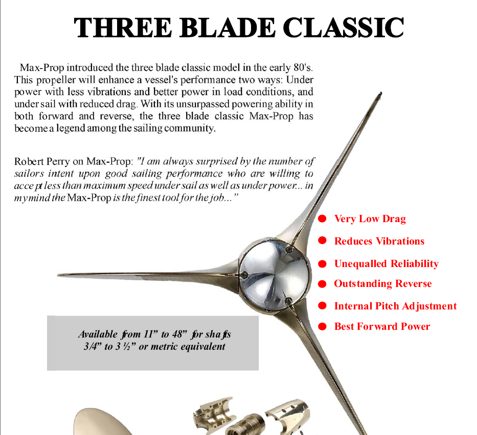
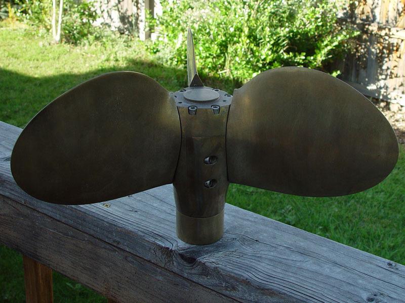
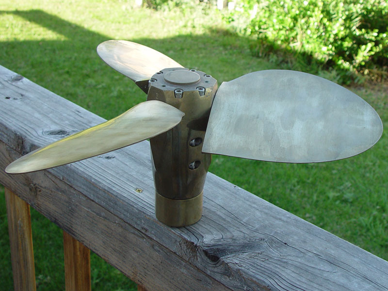
With the increased popularity of the cruising vessel, Max-Prop introduced the three blade classic model in the early 80's. This propeller will enhance a vessel's performance both under power with less vibrations, better power in load conditions and under sail with reduced drag. With its unsurpassed powering ability in both forward and reverse, the three blade classic Max-Prop has become a legend among the sailing community. While Standard equipment on some of the world's most famous yachts (Swan, Little Harbor, Hinckley, Alden, Baltic, etc.), the three blade classic is also a proven choice for the more modest common cruiser.
- Best Forward Power
- Reduces Vibrations
- Outstanding Reverse
- Uneqaled Reliability
- Very Low Drag
- Internal Adjustable Pitch
- Available from 11" to 44" for shafts 3/4" to 3" or metric equivalent.
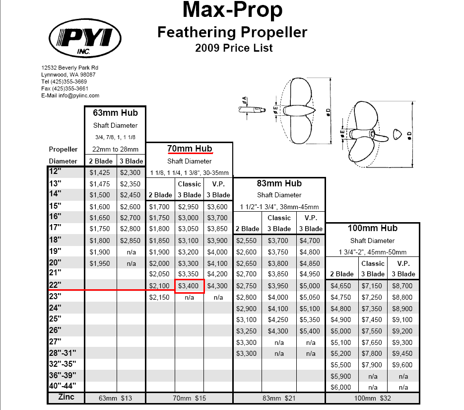
With the increased popularity of the cruising vessel, Max-Prop introduced it's three blade classic model in the early 80's. This propeller will enhance a vessel's performance both under power with less vibrations, better power in load conditions and under sail with reduced drag. With its unsurpassed powering ability in both forward and reverse, the three blade classic Max-Prop has become a legend among the sailing community. This propeller is designed to fit 1 1/4" to 1 3/8" (30mm to 35mm) Shafts.
3. INSTALLATION
| Installation ManualsThis instruction booklet is designed to answer all your questions on assembly of the Max Prop. Please read it carefully and assemble the propeller at least once before installing it on your boat. |

1) 3 BLADE ASSEMBLY: Make sure that if you receive more than one propeller that you do not interchange parts. Each propeller is individually balanced and if interchanged it will be put out of balance. Please use figure 3 in the instruction book for part number references.

A) Fit the hub (1) to the propeller shaft (2). Be sure that the key (3) is the proper dimension and that the hub slides completely onto the shaft. If you are not sure, remove the key and slide the hub onto the shaft making a mark on the shaft where the hub stops on the shaft. Re-insert the key and slide the hub on to the shaft, if it slides up to your mark , it is fine. If not, you will need to file down the sides or top of the key until the hub slides completely onto the shaft.
B) Tighten the nut (A) onto the shaft. Align the groves in the base of the nut with the groves in the central hub, so as to obtain two complete holes allowing insertion of the pins (B). Insert the pins, then rotate the pins are as shown in the drawing below, so as not to interfere with the inserting of the central cone gear. One thread can be exposed aft of the nut, if more than that is showing it will be necessary to cut off the excess with a hack saw. If too many threads are exposed it will raise the central cone gear (6) and effect the performance of the propeller.

C) Insert the central cone gear (6) into the central hub (1) as shown in figure 3VP. The cone gear has a block between two teeth, this is the "X" mark. It will fit into the central hub at only one place, where there is a gap in the gear teeth.
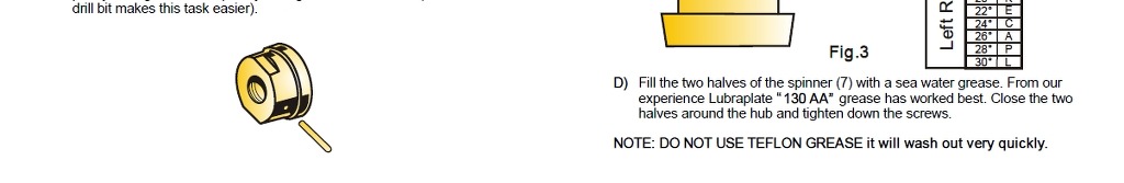
D) Fill the two halves of the spinner (7) with grease. We recommend Lubraplate model 130AA grease. Close the two halves around the hub and tighten down the screws.
NOTE: DO NOT USE TEFLON GREASE it will wash out very quickly.
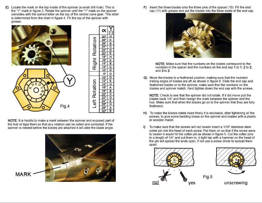
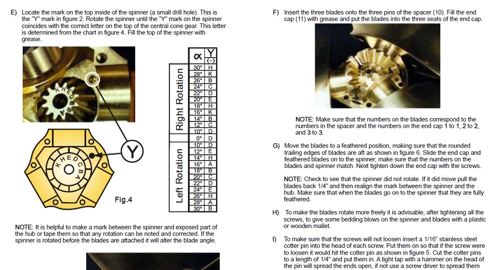
E) Locate the mark on the top inside of the spinner (a small drill hole). This is the "Y" mark in the drawing below. Rotate the spinner until the "Y" mark on the spinner coincides with the correct letter on the top of the cone gear. "R" is for a right hand rotation shaft and "L" is for a left hand rotation shaft. (Shaft rotation is determined from the stern of the boat looking forward).
NOTE: It is helpful to make a mark between the spinner and the exposed part of the central hub, or tape them so that any rotation can be noted and corrected. If the spinner is rotated before the blades are attached it will alter the blade angle.

F) Insert the three blades onto the three pins of the spacer (10). Fill the end cap (11) with grease and put the blades into the three seats of the end cap.
NOTE: Make sure that the numbers on the blades correspond to the numbers on the spacer and the numbers on the end cap 1 to 1, 2 to 2, and 3 to 3.
G) Move the blades to the feathered position, making sure that the rounded trailing edges of the blades are aft as shown in figure 3 of the instruction manual. Slide the end cap and feathered blades onto the spinner, make sure that the numbers on the blades and spinners match. Next tighten down the end cap with the screws.
NOTE: Check to see that the spinner did not rotate. If it did pull the blades back 1/4" and then realign the mark between the spinner and hub. Make sure that when the blades go on to the spinner that they are fully feathered.
H) To make the blades rotate more freely it is advisable, after tightening all the screws, to give some bedding blows on the spinner and blades with a plastic or wooden mallet.
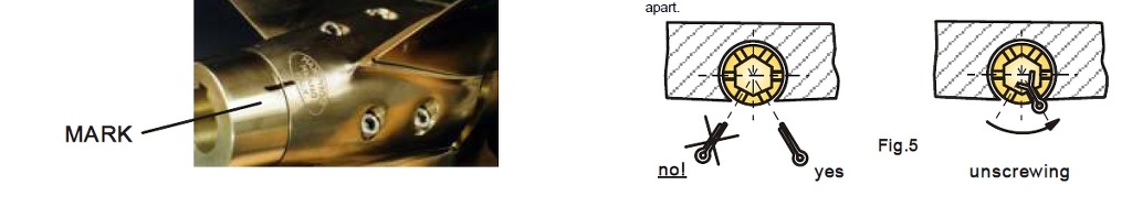
I) To make sure that the screws will not loosen insert a cotter pin into the head of each screw. Put them in so that if the screw were to loosen it would hit the cotter pin as shown in figure 5 of the instruction manual. Cut the cotter pins to a length of 1/4" and put them in. A light tap with a hammer on the head of the pin will spread the ends open, it not use a screw driver to spread them apart.

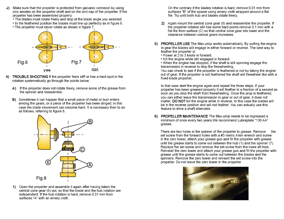
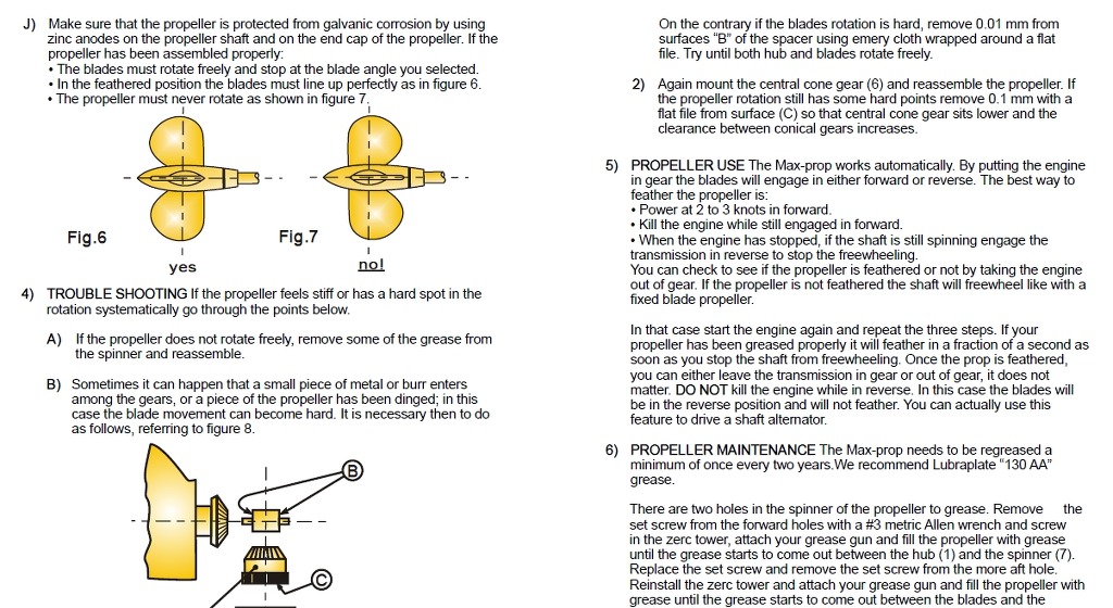
J) Make sure that the propeller is protected from electrolytic corrosion by using "mil spec" zinc anodes on the propeller shaft. If the propeller has been assembled properly:
- The blades must rotate freely and stop at the blade angle you selected.
- In the feathered position the blades must line up perfectly as in figure 6.
- The propeller must never rotate as shown in figure 7.

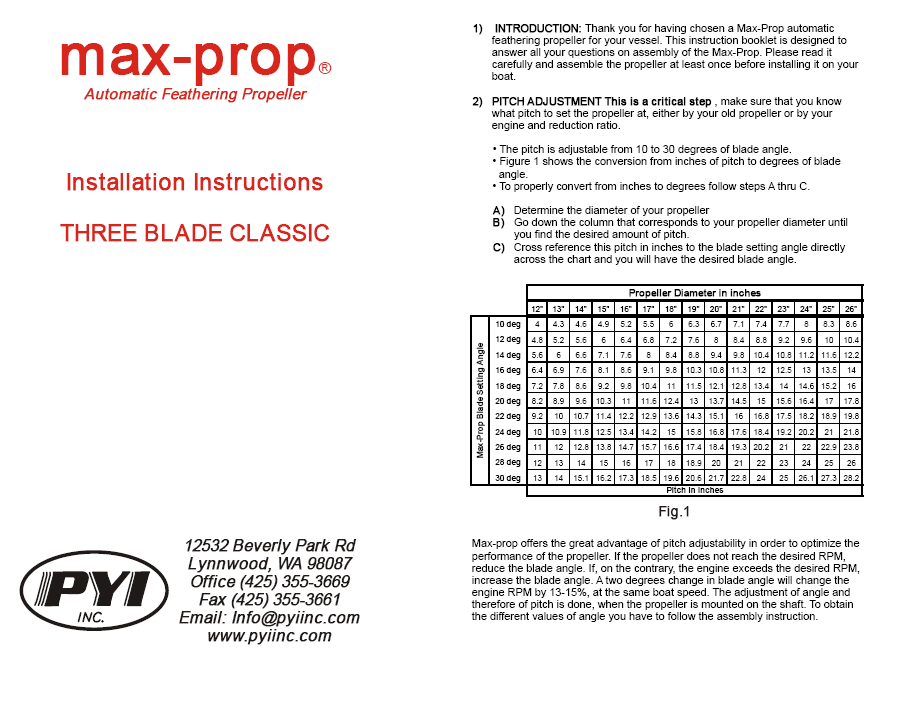
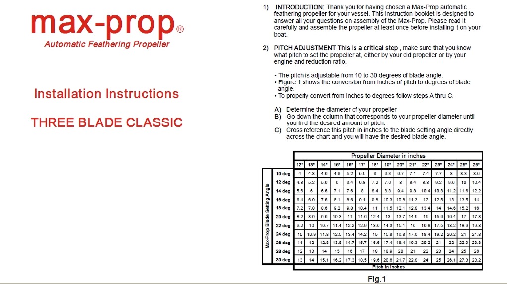
2) PITCH ADJUSTMENT This is a critical step, make sure that you know what pitch to set the propeller at, either by your old propeller or by your engine and reduction ratio.
- The pitch is adjustable from 10 to 30 degrees of blade angle.
- Figure 1 shows the conversion from inches of pitch to degrees of blade angle.
- To properly convert from inches to degrees follow steps A thru C.
A) Determine the diameter of your propeller
B) Go down the column that corresponds to your propeller diameter until you find the desired amount of pitch.
C) Cross reference this pitch in inches to the blade setting angle directly across the chart and you will have the desired blade angle.
Propeller Diameter | |||||||||||||
15" | 16" | 17" | 18" | 19" | 20" | 21" | 22" | 23" | 24" | 25" | 26" | ||
B | 10o | 4.9 | 5.2 | 5.5 | 6.0 | 6.3 | 6.7 | 7.1 | 7.4 | 7.7 | 8.0 | 8.3 | 8.6 |
L | 11o | 5.5 | 5.8 | 6.2 | 6.6 | 7.0 | 7.4 | 7.8 | 8.1 | 8.5 | 8.8 | 9.2 | 9.5 |
A | 12o | 6.0 | 6.4 | 6.8 | 7.2 | 7.6 | 8.0 | 8.4 | 8.8 | 9.2 | 9.6 | 10.0 | 10.4 |
D | 13o | 6.6 | 7.0 | 7.4 | 7.8 | 8.2 | 8.7 | 9.1 | 9.6 | 10.0 | 10.4 | 10.8 | 11.3 |
E | 14o | 7.1 | 7.6 | 8.0 | 8.4 | 8.8 | 9.4 | 9.8 | 10.4 | 10.8 | 11.2 | 11.6 | 12.2 |
15o | 7.6 | 8.1 | 8.6 | 9.1 | 9.6 | 10.1 | 10.6 | 11.2 | 11.7 | 12.1 | 12.6 | 13.1 | |
S | 16o | 8.1 | 8.6 | 9.1 | 9.8 | 10.3 | 10.8 | 11.3 | 12.0 | 12.5 | 13.0 | 13.5 | 14.0 |
E | 17o | 8.7 | 9.2 | 9.8 | 10.4 | 10.9 | 11.5 | 12.1 | 12.7 | 13.3 | 13.8 | 14.4 | 15.0 |
T | 18o | 9.2 | 9.8 | 10.4 | 11.0 | 11.5 | 12.1 | 12.8 | 13.4 | 14.0 | 14.6 | 15.2 | 16.0 |
T | 19o | 9.8 | 10.4 | 11.0 | 11.7 | 12.3 | 12.9 | 13.7 | 14.2 | 14.8 | 15.5 | 16.1 | 16.9 |
I | 20o | 10.3 | 11.0 | 11.6 | 12.4 | 13.0 | 13.7 | 14.5 | 15.0 | 15.6 | 16.4 | 17.0 | 17.8 |
N | 21o | 10.9 | 11.6 | 12.3 | 13.0 | 13.7 | 14.4 | 15.3 | 15.9 | 16.6 | 17.3 | 18.0 | 18.8 |
G | 22o | 11.4 | 12.2 | 12.9 | 13.6 | 14.3 | 15.1 | 16.0 | 16.8 | 17.5 | 18.2 | 18.9 | 19.8 |
23o | 12.0 | 12.8 | 13.6 | 14.3 | 15.1 | 16.0 | 16.8 | 17.6 | 18.4 | 19.2 | 20.0 | 20.8 | |
A | 24o | 12.5 | 13.4 | 14.2 | 15.0 | 15.8 | 16.8 | 17.6 | 18.4 | 19.2 | 20.2 | 21.0 | 21.8 |
N | 25o | 13.2 | 14.1 | 15.0 | 15.8 | 16.6 | 17.6 | 18.5 | 19.3 | 20.1 | 21.1 | 22.0 | 22.8 |
G | 26o | 13.8 | 14.7 | 15.7 | 16.6 | 17.4 | 18.4 | 19.3 | 20.2 | 21.0 | 22.0 | 22.9 | 23.8 |
L | 27o | 14.4 | 15.4 | 16.4 | 17.3 | 18.2 | 19.2 | 20.2 | 21.1 | 22.0 | 23.0 | 24.0 | 24.9 |
E | 28o | 15.0 | 16.0 | 17.0 | 18.0 | 18.9 | 20.0 | 21.0 | 22.0 | 23.0 | 24.0 | 25.0 | 26.0 |
29o | 15.6 | 16.7 | 17.8 | 18.8 | 19.8 | 20.9 | 21.9 | 23.0 | 24.0 | 25.1 | 26.2 | 27.1 | |
30o | 16.2 | 17.3 | 18.5 | 19.6 | 20.6 | 21.7 | 22.8 | 24.0 | 25.0 | 26.1 | 27.3 | 28.2 | |
Inches of pitch | |||||||||||||
Pitch adjustment is very simple on the V.P. model, and can be done with the boat in or out of the water in a matter of seconds. Refer to the figure below.
Once you have determined the pitch and rotation to set the propeller at, pull back on the adjustment ring and rotate it to the correct degree of blade angle for that rotation. Once the correct setting aligns with the degree reference mark push it back into place. The pitch is now set. As an example the setting for the propeller in the drawing below is 18o for a right hand rotation propeller or 22o for a left hand rotation propeller.

Figure 2 below shows degrees of blade angle not inches of pitch.
To convert from inches of pitch to blade angle use figure 1.
3) TROUBLE SHOOTING If the propeller feels stiff or has a hard spot in the rotation systematically go through the points below.
A) If the propeller does not rotate freely, remove some of the grease from the spinner and reassemble.
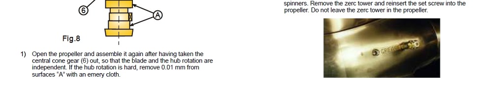
B) Sometimes it can happen that a small piece of metal or a burr enters the gears, or a piece of the propeller has been dinged; in this case the blade movement can become hard. It is necessary then to do as follows, referring to figure 8.
1) Open the propeller and assemble it again after having taken the central cone gear (6) out, so that the blade and the hub rotation are independent. If the hub rotation is hard, remove 0.01 mm from surfaces "A" with an emery cloth. On the contrary if the blades rotation is hard, remove 0.01 mm from surfaces "B" of the spacer using emery cloth wrapped around a flat file. Try until both hub and blades rotate freely.
2) Again mount the central cone gear (6) and reassemble the propeller. If the propeller rotation still has some hard points remove 0.1 mm with a flat file from surface (C) so that central cone gear sits lower and the clearance between conical gears increases.

4) PROPELLER USE The Max Prop works automatically. By putting the engine in gear the blades will engage in either forward or reverse. The best way to feather the propeller is;
- Power at 2 to 3 knots in forward.
- Kill the engine while still engaged in forward.
- When the engine has stopped, if the shaft is still spinning engage the transmission in reverse to stop the freewheeling.
You can check to see if the propeller is feathered or not by taking the engine out of gear. If the propeller is not feathered the shaft will freewheel like with a fixed blade propeller.
In that case start the engine again and repeat the three steps. If your propeller has been greased properly it will feather in a fraction of a second as soon as you stop the shaft from freewheeling. Once the prop is feathered, you can either leave the transmission in gear or out of gear, it does not matter. DO NOT kill the engine while in reverse. In this case the blades will be in the reverse position and will not feather. You can actually use this feature to drive a shaft alternator.
|
5) PROPELLER MAINTENANCE The Max Prop needs to be regreased a minimum of once every two years. We recommend Lubraplate "130 AA" Grease, it is inexpensive and performs better than many other greases.
There are two holes in the spinner of the propeller to grease. Remove the set screw from the forward hole with a #3 metric Allen wrench and screw in the zerc tower, attach your grease gun and fill the propeller with grease until the grease starts to come out between the hub (#1) and the spinners. Replace the set screw and remove the set screw from the more aft hole. Reinstall the zerc tower and attach your grease gun and fill the propeller with grease until the grease starts to come out between the blades and the spinners. Remove the zerc tower and reinsert the set screw into the propeller. Do not leave the zerc tower in the propeller.
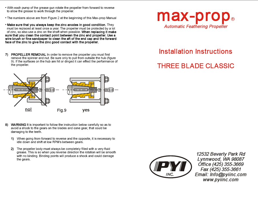
- With each pump of the grease gun rotate the propeller from forward to reverse to allow the grease to work through the propeller.
- The numbers above are from Figure 3 at the beginning of this Max-Prop Manual.
- Make sure that you always keep the zinc anodes in good condition. They must be replaced at least once a year or as needed. The propeller must be protected by a lot of zinc. When replacing it make sure that you clean the contact point between the zinc and propeller shaft. Use a wire brush or fine sandpaper to clean the shaft and the inside diameter of the zinc to give the zinc good contact with the propeller.
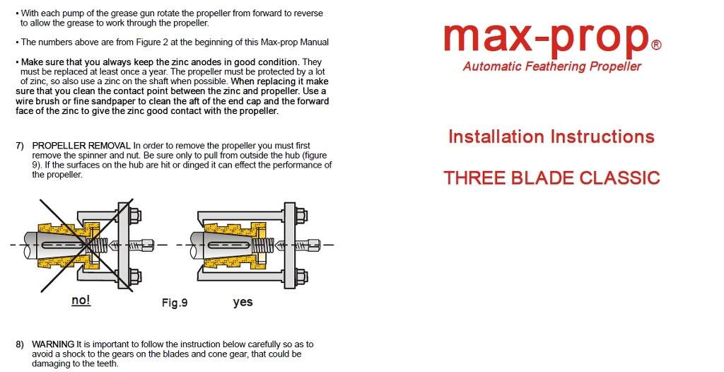
6) PROPELLER REMOVAL In order to remove the propeller you must first remove the spinner and nut. Be sure only to pull from outside the hub (figure 9). If the surfaces on the hub are hit or dinged it can effect the performance of the propeller.

7) WARNING It is important to follow the instruction below carefully so as to avoid a shock to the gears on the blades and cone gear, that could be damaging to the teeth.
- The pitch is adjustable from 10 to 30 degrees of blade angle.
- Figure 1 shows the conversion from inches of pitch to degrees of blade angle.
- To properly convert from inches to degrees follow steps A thru C.
- The blades must rotate freely and stop at the blade angle you selected.
- In the feathered position the blades must line up perfectly as in figure 6.
- The propeller must never rotate as shown in figure 7.
- Power at 2 to 3 knots in forward.
- Kill the engine while still engaged in forward.
- When the engine has stopped, if the shaft is still spinning engage the transmission in reverse to stop the freewheeling.
- With each pump of the grease gun rotate the propeller from forward to reverse to allow the grease to work through the propeller.
- The numbers above are from Figure 3 at the beginning of this Max-Prop Manual.
- Make sure that you always keep the zinc anodes in good condition.They must be replaced at least once a year or as needed. The propeller must be protected by a lot of zinc. When replacing it make sure that you clean the contact point between the zinc and propeller shaft. Use a wire brush or fine sandpaper to clean the shaft and the inside diameter of the zinc to give the zinc good contact with the propeller.
1) When going from forward to reverse and the opposite, it is necessary to idle down and shift at low RPM's between gears.
2) The propeller body must always be completely filled with a very fluid grease. This is so when you reverse direction the rotation will be smooth with no binding. Binding points will produce a shock and could damage the gears.
| 2 Blade Classic Installation Mannual |
This instruction booklet is designed to answer all your questions on assembly of the Max Prop. Please read it carefully and assemble the propeller at least once before installing it on your boat.
1) PITCH ADJUSTMENT This is a critical step, make sure that you know what pitch to set the propeller at, either by your old propeller or by your engine and reduction ratio.
A) Determine the diameter of your propeller
B) Go down the column that corresponds to your propeller diameter until you find the desired amount of pitch.
C) Cross reference this pitch in inches to the blade setting angle directly across the chart and you will have the desired blade angle.
Propeller Diameter | ||||||||||||||||
12" | 13" | 14" | 15" | 16" | 17" | 18" | 19" | 20" | 21" | 22" | 23" | 24" | 25" | 26" | ||
B | 10o | 4 | 4.3 | 4.6 | 4.9 | 5.2 | 5.5 | 6.0 | 6.3 | 6.7 | 7.1 | 7.4 | 7.7 | 8.0 | 8.3 | 8.6 |
L | 12o | 4.8 | 5.2 | 5.6 | 6.0 | 6.4 | 6.8 | 7.2 | 7.6 | 8.0 | 8.4 | 8.8 | 9.2 | 9.6 | 10.0 | 10.4 |
A | 14o | 5.6 | 6 | 6.6 | 7.1 | 7.6 | 8.0 | 8.4 | 8.8 | 9.4 | 9.8 | 10.4 | 10.8 | 11.2 | 11.6 | 12.2 |
D | 16o | 6.4 | 6.9 | 7.6 | 8.1 | 8.6 | 9.1 | 9.8 | 10.3 | 10.8 | 11.3 | 12.0 | 12.5 | 13.0 | 13.5 | 14.0 |
E | 18o | 7.2 | 7.8 | 8.6 | 9.2 | 9.8 | 10.4 | 11.0 | 11.5 | 12.1 | 12.8 | 13.4 | 14.0 | 14.6 | 15.2 | 16.0 |
| 20o | 8.2 | 8.9 | 9.6 | 10.3 | 11.0 | 11.6 | 12.4 | 13.0 | 13.7 | 14.5 | 15.0 | 15.6 | 16.4 | 17.0 | 17.8 |
A | 22o | 9.2 | 10 | 10.7 | 11.4 | 12.2 | 12.9 | 13.6 | 14.3 | 15.1 | 16.0 | 16.8 | 17.5 | 18.2 | 18.9 | 19.8 |
N | 24o | 10 | 10.9 | 11.8 | 12.5 | 13.4 | 14.2 | 15.0 | 15.8 | 16.8 | 17.6 | 18.4 | 19.2 | 20.2 | 21.0 | 21.8 |
G | 26o | 11 | 12 | 12.8 | 13.8 | 14.7 | 15.7 | 16.6 | 17.4 | 18.4 | 19.3 | 20.2 | 21.0 | 22.0 | 22.9 | 23.8 |
L | 28o | 12 | 13 | 13.9 | 15.0 | 16.0 | 17.0 | 18.0 | 18.9 | 20.0 | 21.0 | 22.0 | 23.0 | 24.0 | 25.0 | 26.0 |
E | 30o | 13 | 14 | 15.1 | 16.2 | 17.3 | 18.5 | 19.6 | 20.6 | 21.7 | 22.8 | 24.0 | 25.0 | 26.1 | 27.3 | 28.2 |
Inches of pitch | ||||||||||||||||
The blade angle is set when the hub of the propeller is mounted on the shaft. To set blade angle you must use the letter configuration in figure 2 that corresponds to your desired blade angle and the rotation of your shaft. The same propeller can be used for either right or left hand rotation.
NOTE: The adjustability allows you optimize the performance of the propeller.
Figure 2 below shows degrees of blade angle not inches of pitch.
To convert from inches of pitch to blade angle use figure 1.
| /\ ___ | Pitch | X | Y | |
in Degrees | ( - ) | ( . ) | (..) | ||
30o | H | H | V | ||
28o | D | K | Z | ||
26o | V | B | N | ||
24o | S | C | P | ||
22o | N | D | S | ||
20o | K | E | T | ||
18o | E | H | V | ||
16o | C | K | Z | ||
14o | T | B | N | ||
12o | P | C | P | ||
10o | L | D | S | ||
0o | K | D | S | ||
10o | H | D | S | ||
12o | D | E | T | ||
14o | B | H | V | ||
16o | S | A | L | ||
18o | N | B | N | ||
20o | K | C | P | ||
22o | E | D | S | ||
24o | C | E | T | ||
26o | A | H | V | ||
28o | P | A | L | ||
30o | L | B | N | ||

If the engine does not reach the desired RPM reduce the blade angle.
If the engine exceeds the desired RPM increase the blade angle.
A two degree change in blade angle will change the engine RPM by 13-15%, at the same boat speed.
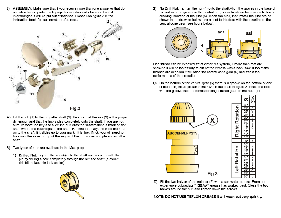
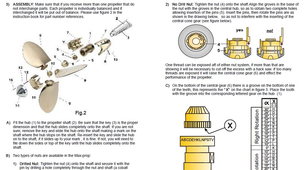
2) 2 BLADE ASSEMBLY: Make sure that if you receive more than one propeller that you do not interchange parts. Each propeller is individually balanced and if interchanged it will be put out of balance. Please use figure 3 in the instruction book for part number references.

A) Fit the hub (1) to the propeller shaft (2). Be sure that the key (3) is the proper dimension and that the hub slides completely onto the shaft. If you are not sure, remove the key and slide the hub onto the shaft making a mark on the shaft where the hub stops on the shaft. Re-insert the key and slide the hub on to the shaft, if it slides up to your mark , it is fine. If not, you will need to file down the sides or top of the key until the hub slides completely onto the shaft.
B) Two types of nuts are available in the Max-Prop:
1) Drilled Nut: Tighten the nut (4) onto the shaft and secure it with the pin (5) by drilling a hole completely through the nut and shaft (a cobalt drill bit makes this task easier).
2) No Drill Nut: Tighten the nut (A) onto the shaft. Align the groves in the base of the nut with the groves in the central hub, so as to obtain two complete holes allowing insertion of the pins (B). Insert the pins, then rotate the pins are as shown in the drawing below, so as not to interfere with the inserting of the central cone gear.(see Figure Below)
One thread can be exposed aft of either nut system, if more than that are showing it will be necessary to cut off the excess with a hack saw. If too many threads are exposed it will raise the central cone gear (6) and effect the performance of the propeller.
C) On the bottom of the central gear (6) there is a groove on the bottom of one of the teeth, this represents the "X" on the chart in figure 2. Place the tooth with the groove into the corresponding lettered gear on the hub (1).
D) Next engage the gears on the blades with those of the central cone gear as shown in figure 2. When engaging the gears make sure that the correct letters on the blades are inserted into the corresponding"." and ".." in the depth of the teeth of the central cone gear.
NOTE: The letters from "A" to "K" marked on the teeth of one blade must engage with "." On the central cone gear. Also that the letters from "L" to "Z" marked on the teeth of the other blade must engage with ".." on the central cone gear.
E) Keeping the two blades steady and pressed on to the spacer (9), put one half spinner (11) onto the hub. Make sure that the numbers on the blades and the spinner correspond 1 to 1 and 2 to 2. Note: Once one half of the spinner is on you can rotate the blades to make sure that the correct letters on the blades match up with the dots on the central cone gear.
F) Fill the other half of the spinner (11) with a sea water grease. From experience Lubraplate "130 AA" grease has worked the best. Put the second half of the spinner onto the hub. Note: DO NOT USE TEFLON GREASE it will wash out very quickly.
G) Remove the first half of the spinner making sure that the second half is well seated. Grease the first half of the spinner and put it onto the hub and insert all the screws and tighten.
H) To make the blades rotate more freely it is advisable, after tightening all the screws, to give some bedding blows on the spinner and blades with a plastic or wooden mallet.
I) To make sure that the screws will not loosen insert a cotter pin into the head of each screw. Put them on so that if the screw were to loosen it would hit the cotter pin as shown in figure 5. Cut the cotter pins to a length of 1/4" and put them in. A tight tap with a hammer on the head of the pin will spread the ends open, if not use a screw driver to spread them apart.
J) Make sure that the propeller is protected from electrolytic corrosion by using "mil spec" zinc anodes on the propeller shaft. If the propeller has been assembled properly:

3) TROUBLE SHOOTING If the propeller feels stiff or has a hard spot in the rotation systematically go through the points below.
A) If the propeller does not rotate freely, remove some of the grease from the spinner and reassemble.
B) Sometimes it can happen that a small piece of metal or a burr enters the gears, or a piece of the propeller has been dinged; in this case the blade movement can become hard. It is necessary then to do as follows, referring to figure 8.
1) Open the propeller and assemble it again after having taken the central cone gear (6) out, so that the blade and the hub rotation are independent. If the hub rotation is hard, remove 0.01 mm from surfaces "A" with an emery cloth. On the contrary if the blades rotation is hard, remove 0.01 mm from surfaces "B" of the spacer using emery cloth wrapped around a flat file. Try until both hub and blades rotate freely.
2) Again mount the central cone gear (6) and reassemble the propeller. If the propeller rotation still has some hard points remove 0.1 mm with a flat file from surface (C) so that central cone gear sits lower and the clearance between conical gears increases.
4) PROPELLER USE The Max Prop works automatically. By putting the engine in gear the blades will engage in either forward or reverse. The best way to feather the propeller is;
You can check to see if the propeller is feathered or not by taking the engine out of gear. If the propeller is not feathered the shaft will freewheel like with a fixed blade propeller.
In that case start the engine again and repeat the three steps. If your propeller has been greased properly it will feather in a fraction of a second as soon as you stop the shaft from freewheeling. Once the prop is feathered, you can either leave the transmission in gear or out of gear, it does not matter. DO NOT kill the engine while in reverse. In this case the blades will be in the reverse position and will not feather. You can actually use this feature to drive a shaft alternator.
|
5) PROPELLER MAINTENANCE The Max Prop needs to be regreased a minimum of once every two years. We recommend Lubraplate "130 AA" Grease, it is inexpensive and performs better than many other greases.
There are two holes in the spinner of the propeller to grease. Remove the set screw from the forward hole with a #3 metric Allen wrench and screw in the zerc tower, attach your grease gun and fill the propeller with grease until the grease starts to come out between the hub (#1) and the spinners. Replace the set screw and remove the set screw from the more aft hole. Reinstall the zerc tower and attach your grease gun and fill the propeller with grease until the grease starts to come out between the blades and the spinners. Remove the zerc tower and reinsert the set screw into the propeller. Do not leave the zerc tower in the propeller.
6) PROPELLER REMOVAL In order to remove the propeller you must first remove the spinner and nut. Be sure only to pull from outside the hub (figure 9). If the surfaces on the hub are hit or dinged it can effect the performance of the propeller.
7) WARNING It is important to follow the instruction below carefully so as to avoid a shock to the gears on the blades and cone gear, that could be damaging to the teeth.
1) When going from forward to reverse and the opposite, it is necessary to idle down and shift at low RPM?s between gears.
2) The propeller body must always be completely filled with a very fluid grease. This is so when you reverse direction the rotation will be smooth with no binding. Binding points will produce a shock and could damage the gears.
4. INSTALLATION VIDEO
5. 악세사리
Pettit Zinc Coat Barnacle Barrier 1792
 | Designed specifically for underwater use like on a Max-Prop. PYI's testing has found this product to perform well in many water conditions around the world. Zinc Coat is for use only on bare metals such as steel, stainless steel, cast iron, copper, nibral, bronze, galvanized steel and lead. It forms an excellent adhesive bond to underwater metals and running gear and inhibits corrosion on these surfaces. Because of its smooth, hard surface it will self-clean in service. Note: Do not apply antifouling paint over Zinc Coat. Do not apply on the end cap of the Max-Prop where the sacrificial zinc anode makes contact. This product can only be shipped via Ground transportation. SKU ID: MPPAINT
|
LUBRIPLATE #130-AA GREASE
 | 10 ounce tube of Lubraplate 130AA Grease SKU ID: LU130 |
MAX PROP GREASE GUN
 | This grease gun is designed to fit the 10 oz tube of Lubraplate 130AA Grease. It even works under water. SKU ID: MPGUN |
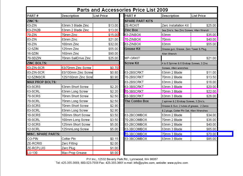
70mm ZINC BOX
 | The Zinc Box includes: 3ea 70mm zincs, 3ea 70mm Zinc Screws, and a #4 Allen wrench for the screws. For 1 1/4" to 1 3/8" (30mm to 35mm) shafts. Screw holes are 2" center to center. SKU ID: 70ZINBOX |
70mm 3B SCREW KIT
 | The Screw Kit includes a full set of screws for your Max-Prop: 4ea spinner screws, 6ea end cap screws, 3ea zinc screws, 10ea cotter pins, 1ea #4 allen wrench, 1ea #5 allen wrench. SKU ID: 703BSCRKT |


